Method And System For Generating A Control System User Interface

a technology of user interface and control system, applied in the direction of program control, ignition automatic control, instruments, etc., can solve the problems of difficult navigation, difficult or time-consuming task of finding the right information in control system, and further complicated task of finding relevant technical information in a large information spa

a technology of user interface and control system, applied in the direction of program control, ignition automatic control, instruments, etc., can solve the problems of difficult navigation, difficult or time-consuming task of finding the right information in control system, and further complicated task of finding relevant technical information in a large information spa

US20100050103A1Active Publication Date: 2010-02-25ABB (SCHWEIZ) AG

Image

  • Method And System For Generating A Control System User Interface
  • Method And System For Generating A Control System User Interface
  • Method And System For Generating A Control System User Interface

Examples


Embodiment Construction

[0044]This invention describes a system for and a method of generating technical information comprising both static and dynamic data in industrial supervision, maintenance and control. The trend towards operation from remote operation centres introduces an increase in both the control room operators' work domain and the workload as several different processes can be supervised and controlled in parallel.

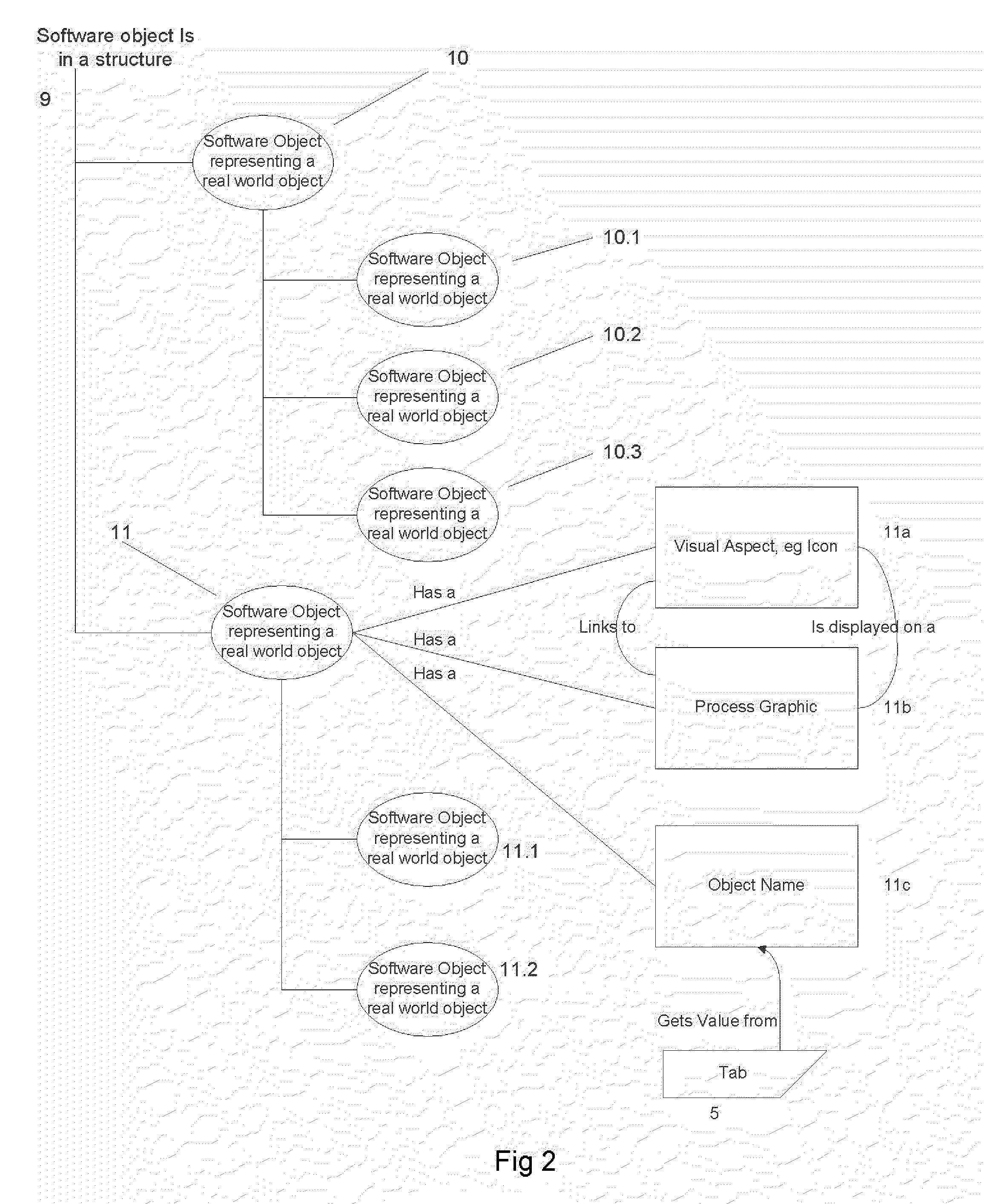
[0045]FIG. 2 shows an arrangement of software entities and a data structure and a naming convention used in this description. FIG. 2 shows a software structure or architecture structure 9 of an industrial control system (not shown) in which are arranged two software objects 10, 11, each of which are also arranged with at least one level of software objects 10.1, 10.2, 10.3 and 11.1-3. A software object may also, as in the case shown for software object 11, comprise one or more software entities called here Aspect objects 11a, 11b, 11c. The software objects 10, 11, each represent some...


PUM


Abstract

A method for providing a user interface for an industrial control system includes a computer and a plurality of process graphics having software objects for controlling and / or monitoring real world objects controlled by the control system. A display of selected process graphics, a designated view arranged with a tab or other selection mechanisms, is automatically generated. The designated view is generated dependent on selecting one or more logical groupings to which control system software objects representing the real world objects belong.

Description

CROSS-REFERENCE TO RELATED APPLICATIONS[0001]The present application is a continuation of pending International patent application PCT / EP2008 / 051647 filed on Feb. 12, 2008 which designates the United States and claims priority from European patent application 07103132.2 filed on Feb. 27, 2007, the content of which is incorporated herein by reference.FIELD OF THE INVENTION[0002]The invention concerns method and system for automatically providing a user interface in an industrial control system.BACKGROUND OF THE INVENTION[0003]In the supervisory control of industrial plants there is continual requirement for information about equipment, current and historic process data, trends, etc. This information is typically provided by the control system and usually in the form of one or more distributed control systems (DCS) and / or supervisory control and data acquisition (SCADA) systems. With the increases in computing power and advances in communication and computerized measurement there is a...

Claims


Application Information

Patent Timeline
25 Feb 2010
Publication
US20100050103A1
IPC
G06F3/048; G05B11/00
CPC
G06F3/0484; G06F9/4443; G06F9/451; G06F3/0481
Inventors
HUSOY, KRISTOFFER; ENKERUD, TORGEIR