
Steam cleaner

Inactive Publication Date: 2010-03-04
TSAI SAM
View PDF4 Cites 49 Cited by
  • Summary
  • Abstract
  • Description
  • Claims
  • Application Information

AI Technical Summary

Benefits of technology

[0003]The primary objective of the present invention is to provide a portable floor steam cleaner that is light-weight and is prepared for operation quickly and easily.

Problems solved by technology

The above methods have drawbacks such as difficult operation, complex mechanical structure or unstable steam generation.

Method used


Image

  • Steam cleaner
  • Steam cleaner
  • Steam cleaner

Examples


Embodiment Construction

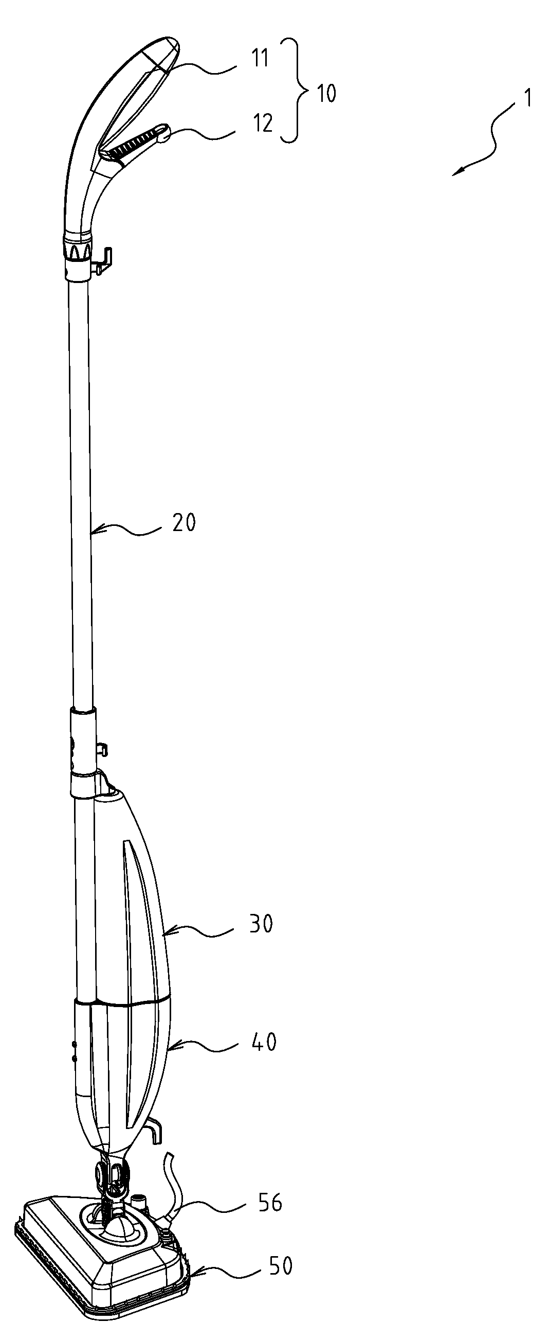
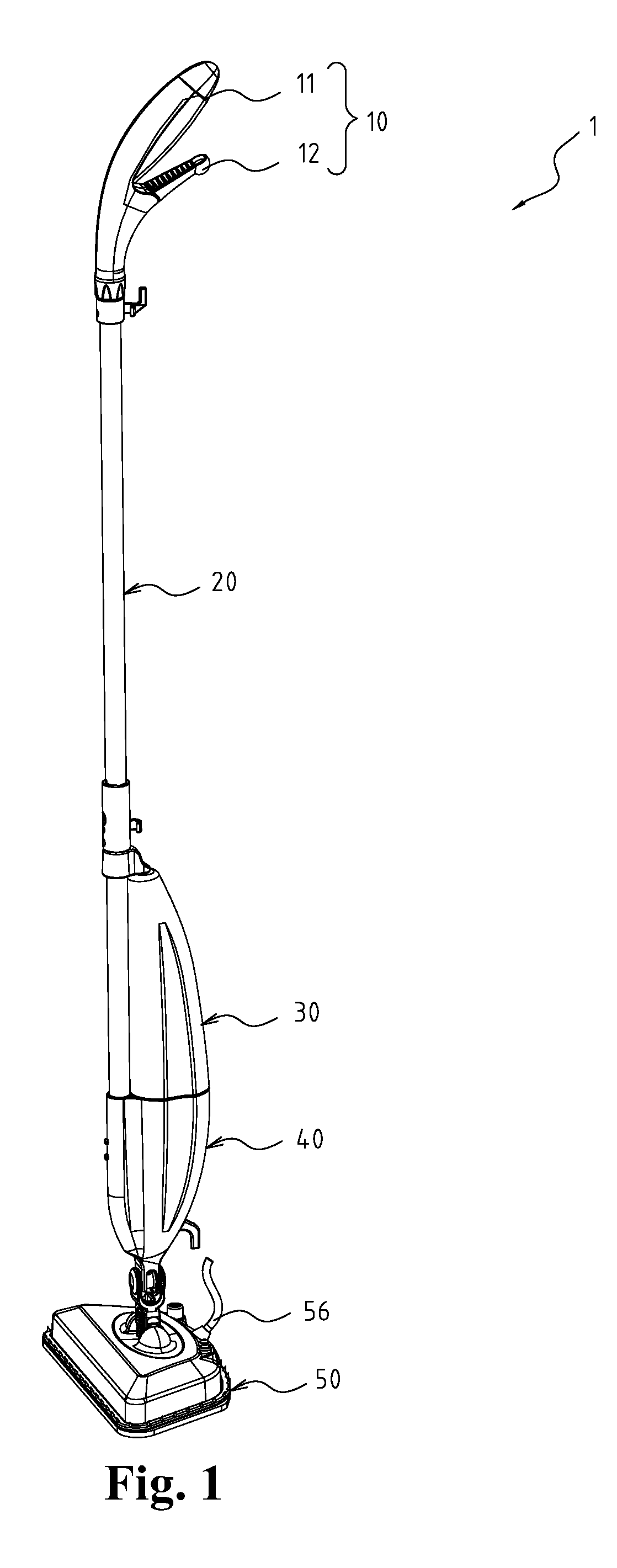
[0012]With reference to FIG. 1, a floor steam cleaner (1) in accordance with the present invention is portable and light-weight, is prepared for operation quickly and easily and comprises a steam head (50), a pivoting connector (40), a reservoir (30), a pole connector (20) and a handle assembly (10).

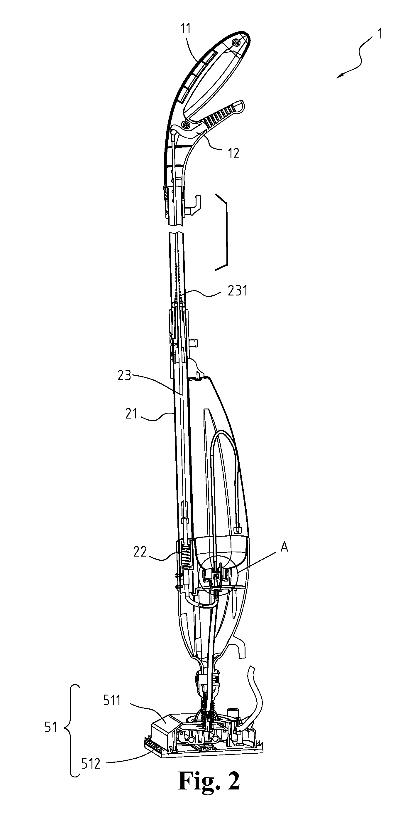
[0013]With further reference to FIGS. 2, 6 and 7, the steam head (50) converts water to steam, sprays steam against a floor surface, has a hollow chamber (51), a steamer (52), a cleaning cover (54), a stationary connector (55) and an electric wire (56). The hollow chamber (51) comprises a top surface (511), a bottom surface (512). The top surface (511) has a center, a bulb (5111), an on / off switch (5112) and an opening. The on / off switch (5112) is connected to the electric wire (56) to activate and deactivate the steamer (52).The opening is formed near the center of the top surface (511). The bottom surface (512) has a center, an outer edge, an inner cavity, a steam port (5121), at least...


PUM


Abstract

The present invention relates to a steam cleaner that is light-weight and is prepared for operation quickly and easily and comprises handle assembly, a pivoting connector, a reservoir, a reservoir socket, a steam head and an electric wire. The handle assembly comprises a grip and a lever. The pivoting connector is attached to the steam head. The reservoir is mounted detachably in the pivoting connector and is easily removed to fill the reservoir with tap water. Squeezing the handle assembly releases water from the reservoir into the steam head where steam is generated to clean a floor.

Description

FIELD OF THE INVENTION[0001]The invention relates to a steam cleaner, particularly to a steam cleaner that operates easily and generates steam stability.BACKGROUND OF THE INVENTION[0002]Conventional floor steam cleaners comprise a steam head, a steam generator and an integral reservoir. Water from the reservoir flows thought the steam generator and is heated to form steam. Steam is useful in removing oil and sticky matter from a floor. Several methods exist to make the water flow into the reservoir. One method uses a valve to control the water inlet. When the valve is open, gravity causes water to flow into the reservoir. Another method uses a pump to control the flow of water. The above methods have drawbacks such as difficult operation, complex mechanical structure or unstable steam generation.SUMMARY OF THE INVENTION[0003]The primary objective of the present invention is to provide a portable floor steam cleaner that is light-weight and is prepared for operation quickly and easil...

Claims


Application Information

Patent Timeline
IPC IPC(8): A47L7/00
CPCA47L13/225A47L13/22
Inventor TSAI, SAM
Owner TSAI SAM
Features
  • Generate Ideas
  • Intellectual Property
  • Life Sciences
  • Materials
  • Tech Scout
  • Unparalleled Data Quality
  • Higher Quality Content
  • 60% Fewer Hallucinations
Learn More