Connecting structures

a technology of connecting structure and seat portion, which is applied in the direction of rail fasteners, snap fasteners, and ways. it can solve the problems of inability to reliably secure the clip base portion to the seat portion of the first component, inability to reliably connect the first component to the second component via the clip, and inability to sufficiently engage the engagement blade of the clip base portion

Inactive Publication Date: 2010-03-04
DAIWA KASEI IND CO LTD
View PDF1 Cites 11 Cited by
  • Summary
  • Abstract
  • Description
  • Claims
  • Application Information

AI Technical Summary

Benefits of technology

[0006]According to the connecting structure thus constructed, when the clip is rotated (i.e., when the at least one engagement blade engages the at least one engagement wall portion), the at least one engagement wall portion can be effectively prevented from being flexed or deformed inwardly because the at least one engagement wall portion can substantially be supported by the support shaft via the at least one rib portion. Therefore, the at least one engagement blade can sufficiently engages the at least one engagement wall portion, so that the clip can be reliably secured to the seat portion of the first component. This means that even if the seat portion is entirely uniformed and thinned in wall thickness, the at least one engagement blade can sufficiently engage the at least one engagement wall portion, so that the clip can be reliably secured to the seat portion of the first component.

Problems solved by technology

As a result, the engagement blades of the clip base portion cannot sufficiently engage the seat portion.
This means that the clip cannot be reliably secured to the seat portion of the first component.
As a result, the first component cannot be reliably connected to the second component via the clip.

Method used


Image

  • Connecting structures
  • Connecting structures
  • Connecting structures

Examples


Embodiment Construction

[0019]Representative examples of the present invention have been described in detail with reference to the attached drawings. This detailed description is merely intended to teach a person of skill in the art further details for practicing preferred aspects of the present invention and is not intended to limit the scope of the invention. Only the claims define the scope of the claimed invention. Therefore, combinations of features and steps disclosed in the foregoing detail description may not be necessary to practice the invention in the broadest sense, and are instead taught merely to particularly describe detailed representative examples of the invention. Moreover, the various features taught in this specification may be combined in ways that are not specifically enumerated in order to obtain additional useful embodiments of the present invention.

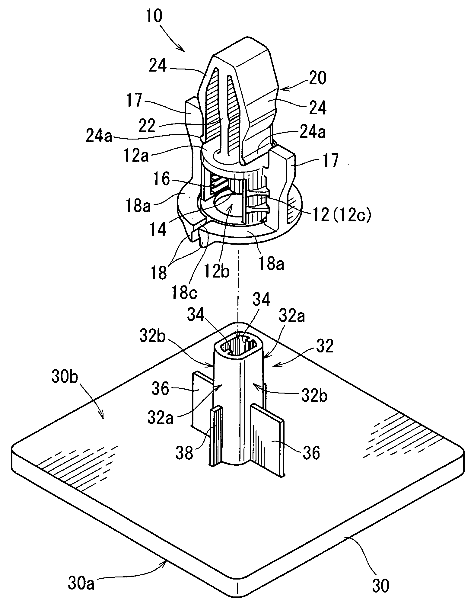
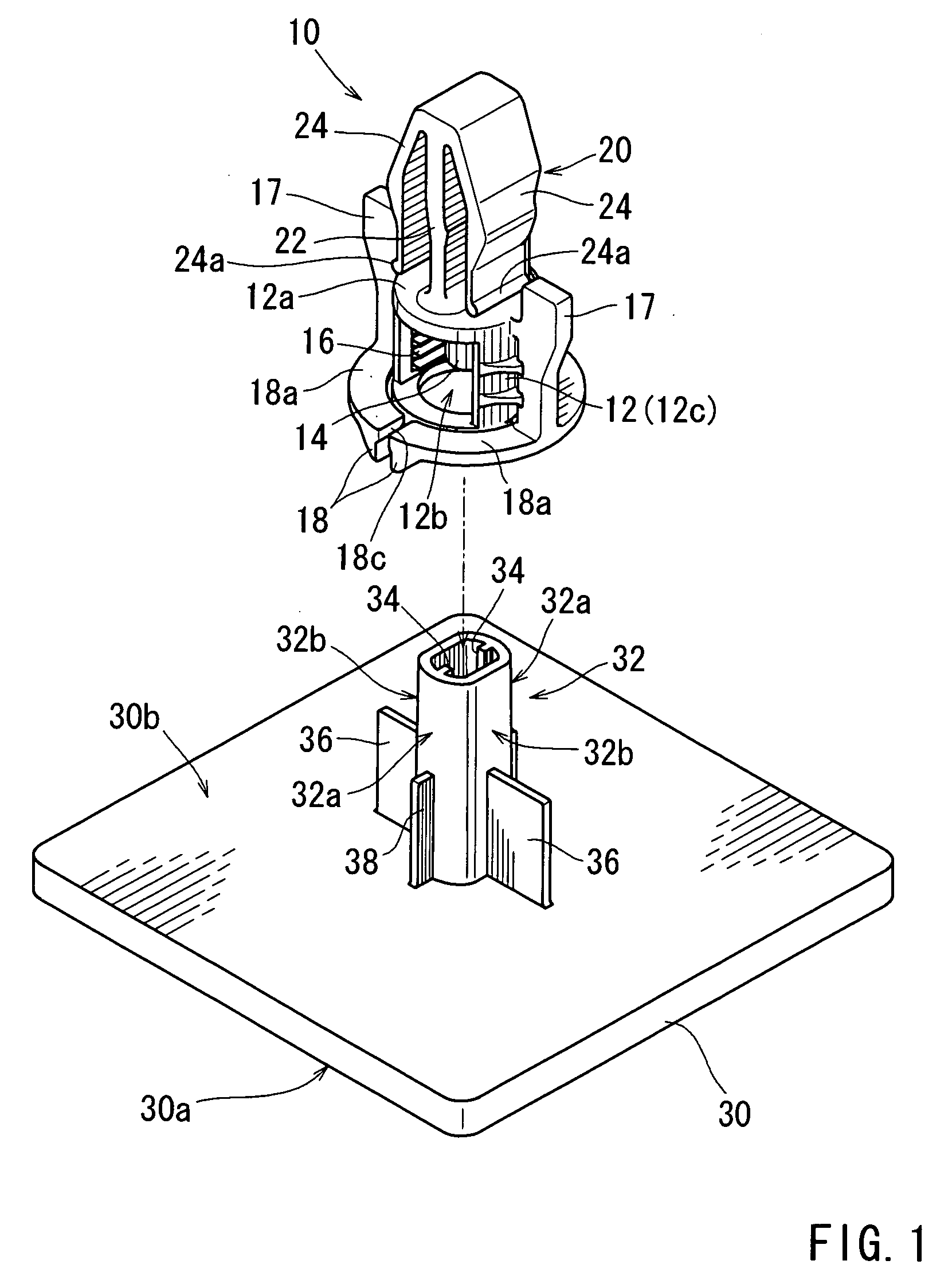
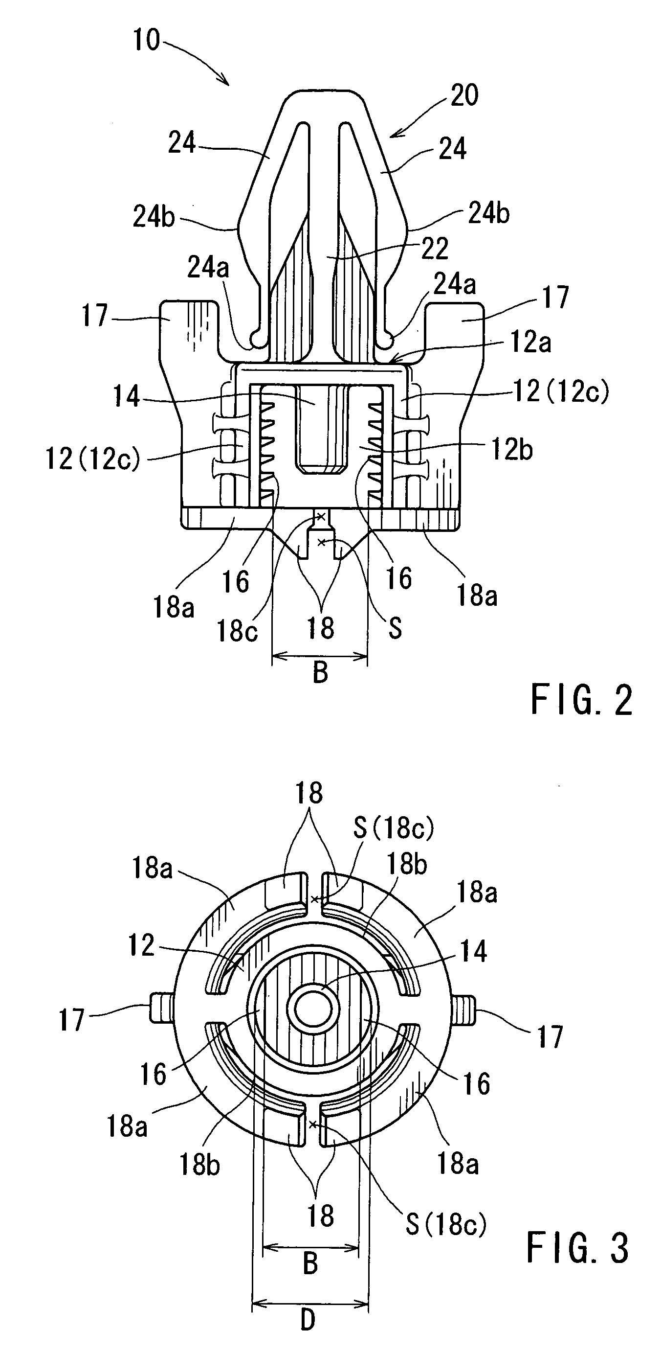
[0020]Detailed representative embodiments of the present invention are shown in FIGS. 1 to 10.

[0021]A first detailed representative emb...


PUM


Abstract

A connecting structure for connecting a first component to a second component may include a clip and a hollow seat portion. The clip is capable of engaging the second component and has a hollow main body. The main body has a support shaft and at least one engagement blade formed therein. The hollow seat portion is integrally formed in the first component and has at least one engagement wall portion. The clip main body is constructed to be placed on the seat portion while the seat portion is introduced thereinto. The support shaft is constructed to be introduced into the seat portion when the clip main body is placed on the seat portion. The at least one engagement wall portion has at least one rib portion that is capable of contacting the support shaft introduced into the seat portion. The at least one engagement blade is arranged and constructed to engage the at least one engagement wall portion when the clip is rotated about an axis thereof, so that the clip can be secured to the seat portion.

Description

FIELD OF THE INVENTION[0001]The present invention relates to connecting structures for connecting two components. More particularly, the present invention relates to connecting structures for connecting a first component to a second component using plastic clips.BACKGROUND OF THE INVENTIONDescription of Related Art[0002]A connecting structure for connecting two components is already known. Such a connecting structure is taught, for example, by Japanese Laid-Open Patent Publication No. 2008-116035. In the connecting structure, a plate-shaped component or first component (e.g., a door trim) has a plurality of cylindrical seat portions each of which is integrally attached to an inner surface of the main portion. Conversely, a clip has a base portion (a main body) and an anchor portion. The base portion has engagement blades that are formed therein.[0003]The clip thus constructed is placed on the seat portion of the first component while the seat portion is introduced into the clip base...

Claims


Application Information

Patent Timeline
Patent Type & Authority Applications(United States)
IPC IPC(8): A44B17/00
CPCB60R11/00B60R13/0206B60R13/0256B60R2011/0052B60R2013/0287F16B5/065Y10T24/309F16B21/02F16B21/075F16B21/08F16B2005/0671Y10T24/45262Y10T24/44026F16B5/0657
Inventor KOMENO, JYUNIWAHARA, TOSHIO
Owner DAIWA KASEI IND CO LTD
Why Eureka
Try Eureka