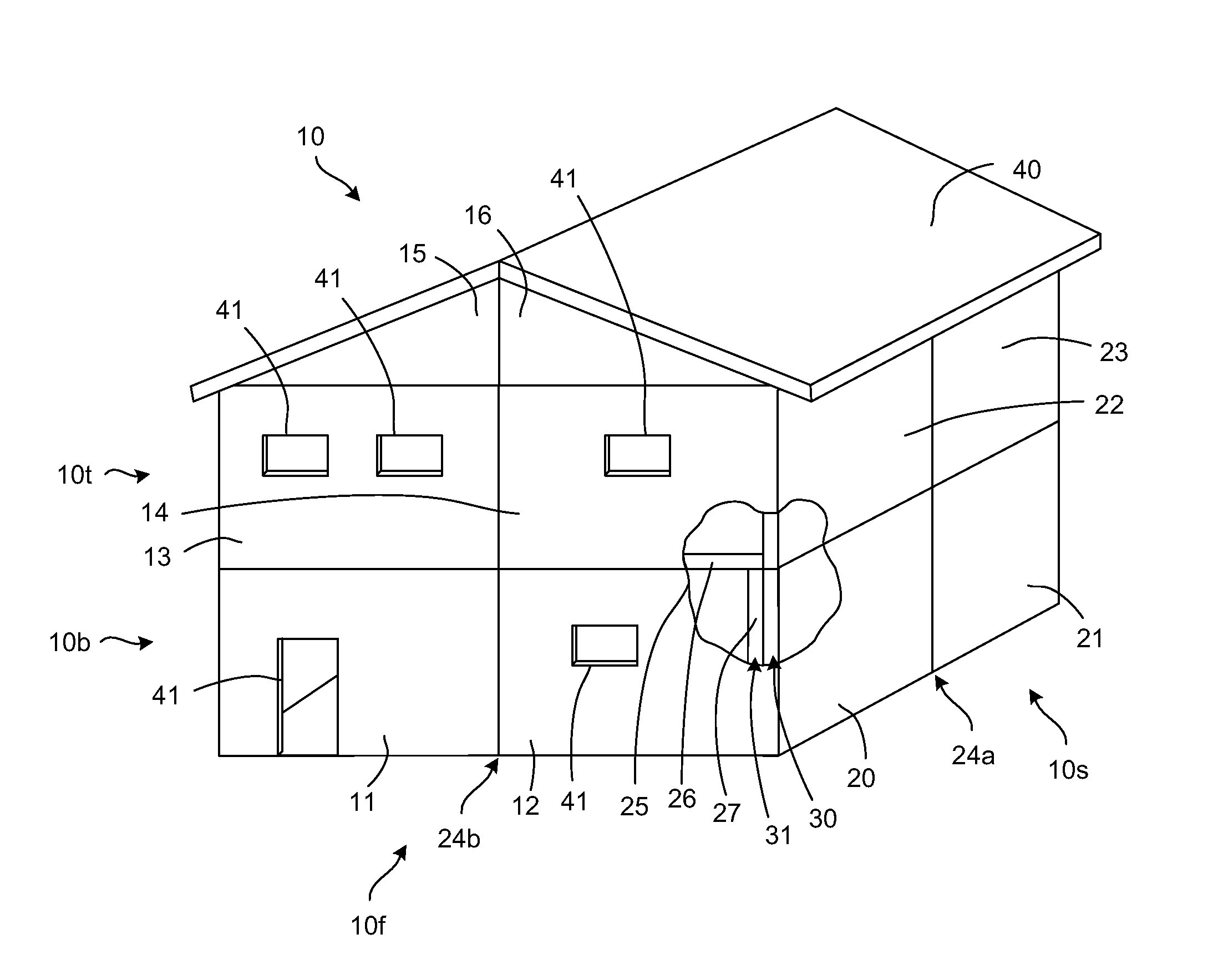
[0005]The present invention provides an alternative to conventional construction materials and techniques. Buildings, such as houses, commercial buildings, warehouses, or other structures can be constructed by composite sandwich panels (also referred to as “sandwich panels” or “composite panels” or “panels”), which have an insulative core and one or more outer
layers. The buildings can be constructed by gluing several sandwich panels together, and usually traditional fasteners, such as screws, rivets, nails, etc., are not needed for such connections. Generally, composite sandwich panels offer a greater strength-to-weight ratio than traditional materials that are used by the
building industry. The composite sandwich panels are generally as strong as, or stronger than, traditional materials including wood-based and steel-based structural insulation panels, while being lighter in weight. Because they weigh less than traditional building materials, the handling and transport of composite sandwich panels is generally less expensive. The composite sandwich panels also can be used to produce light-weight structures, such as floating houses, mobile homes, or travel trailers, etc.
[0006]Sandwich panels generally are more elastic or flexible than conventional materials such as wood, concrete, steel or
brick and, therefore, monolithic (e.g., unitary or single
unit structure) buildings made from sandwich panels generally are more durable than buildings made from conventional materials. For example, sandwich panels also may be non-flammable, waterproof, very strong and durable, and in some cases able to
resist hurricane-force winds (up to 300 Kph (kilometers per hour) or more). The sandwich panels also may be resistant to the detrimental effects of
algae, fungicides, water, and
osmosis. As a result, buildings constructed from sandwich panels may be better able to withstand earthquakes, floods, tornados, hurricanes, fires and other natural disasters than buildings constructed from conventional materials.
[0007]
Sandwich panel structures may be less expensive to build than structures built from conventional materials because of reduced material costs and alternative construction techniques. The ownership and maintenance costs for
sandwich panel structures also may be less over the long term because
sandwich panel structures may last longer and degrade at a slower rate than buildings made from conventional materials. Structures built from sandwich panels therefore may require less maintenance and upkeep than structures built from conventional building materials, which may reduce the overall ownership costs for end users.
[0008]The insulative core of the sandwich panels also may reduce the amount of energy needed to heat and / or cool the building, which may reduce the overall costs to operate the building. The insulative core also may reduce or eliminate the need for additional insulation in the building, as may be necessary to insulate structures built from conventional building materials.
Sandwich panel structures therefore may be less expensive to build and operate than buildings constructed from conventional building materials.
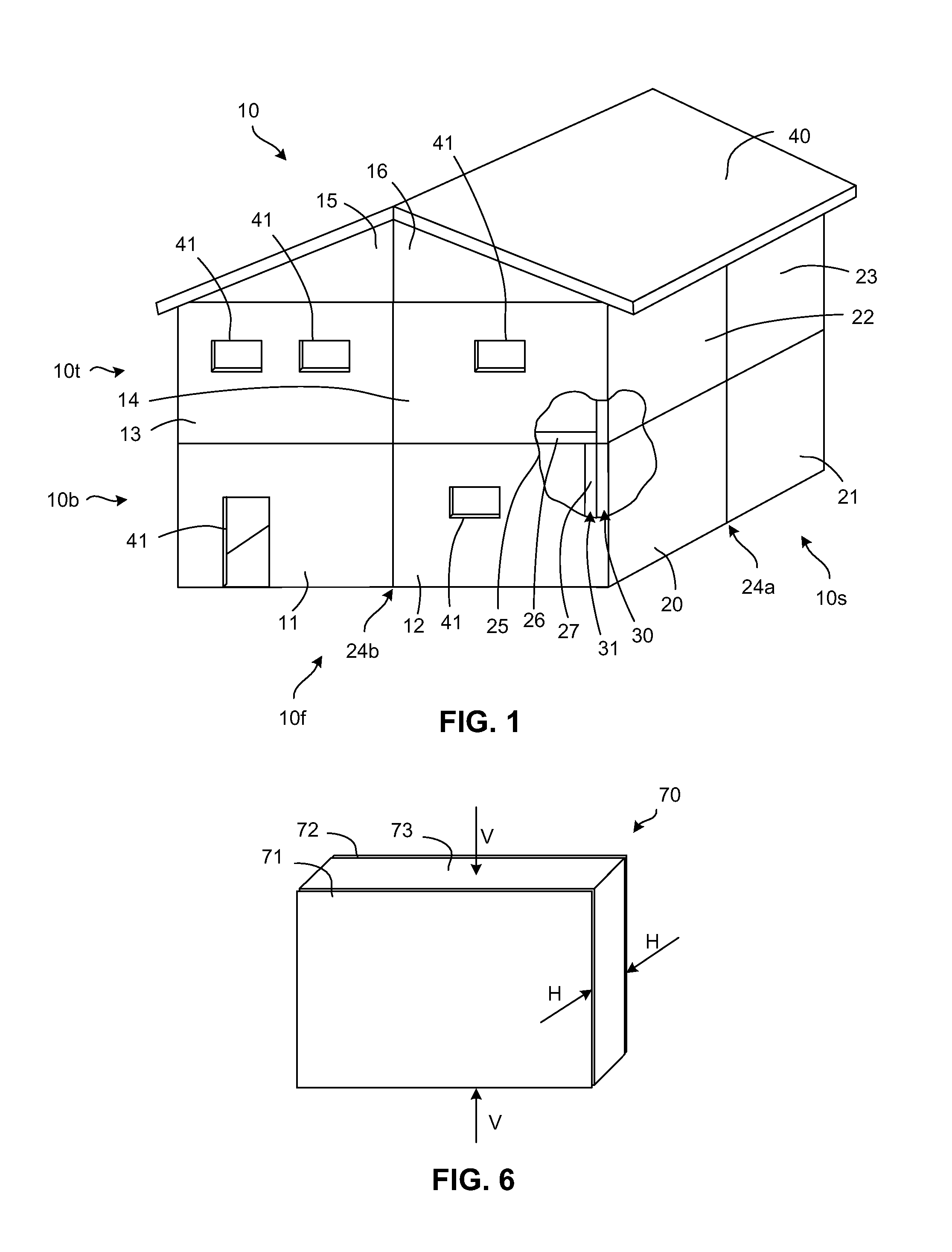
[0009]A number of construction elements, e.g., one or more composite sandwich panels can be connected together, for example, to erect walls, to build ceilings or roofs, or to divide the interior of the building into one or more rooms, etc. As described in more detail below, a number of sandwich panels can be connected together to form a multi-panel
wall segment. A number of multi-panel wall segments can be connected together in a parallel orientation with bonding material to form a
double wall segment (e.g., a
wall segment that is two panels thick). The connections between the multi-panel wall segments are bridged at a joint between the segments. In one embodiment, the connections between the multi-panel wall segments are bridged by a reinforcement member that extends on both sides of the connection between the sandwich panels of the multi-panel wall segments. In another embodiment, the joint is bridged by an offset between the connections of the sandwich panels multi-panel wall segments to form a discontinuous joint. The bridge may provide a reinforcement, strengthening etc., function, and the bridged joint increases the rigidity and stiffness of the wall and also transfers loads between the multi-panel wall segments. The
double wall segment may be used, for example, to support an upper portion or second level of a building or to strengthen the walls of the building, etc.

