
System and method for selective catalytic reduction control

Active Publication Date: 2010-03-04
DELPHI INT OPERATIONS LUXEMBOURG S A R L
View PDF23 Cites 104 Cited by
  • Summary
  • Abstract
  • Description
  • Claims
  • Application Information

AI Technical Summary

Benefits of technology

[0032]wherein step (ii) controls the supply of the required quantit

Problems solved by technology

The calculation load required for this approach is also very high as it would require to calculate multiple complex chemical reactions occurring in the catalyst in slices along its length.
Closed-loop control of such a system is usually realized with NOx sensors before and after the SCR catalyst, but NOx sensors are also sensitive to NH3 creating additional difficulty that is required to be taken into account by the closed-loop control.

Method used


Image

  • System and method for selective catalytic reduction control
  • System and method for selective catalytic reduction control
  • System and method for selective catalytic reduction control

Examples


Embodiment Construction

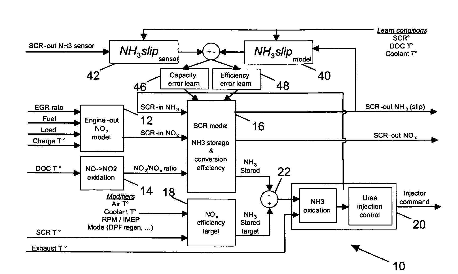
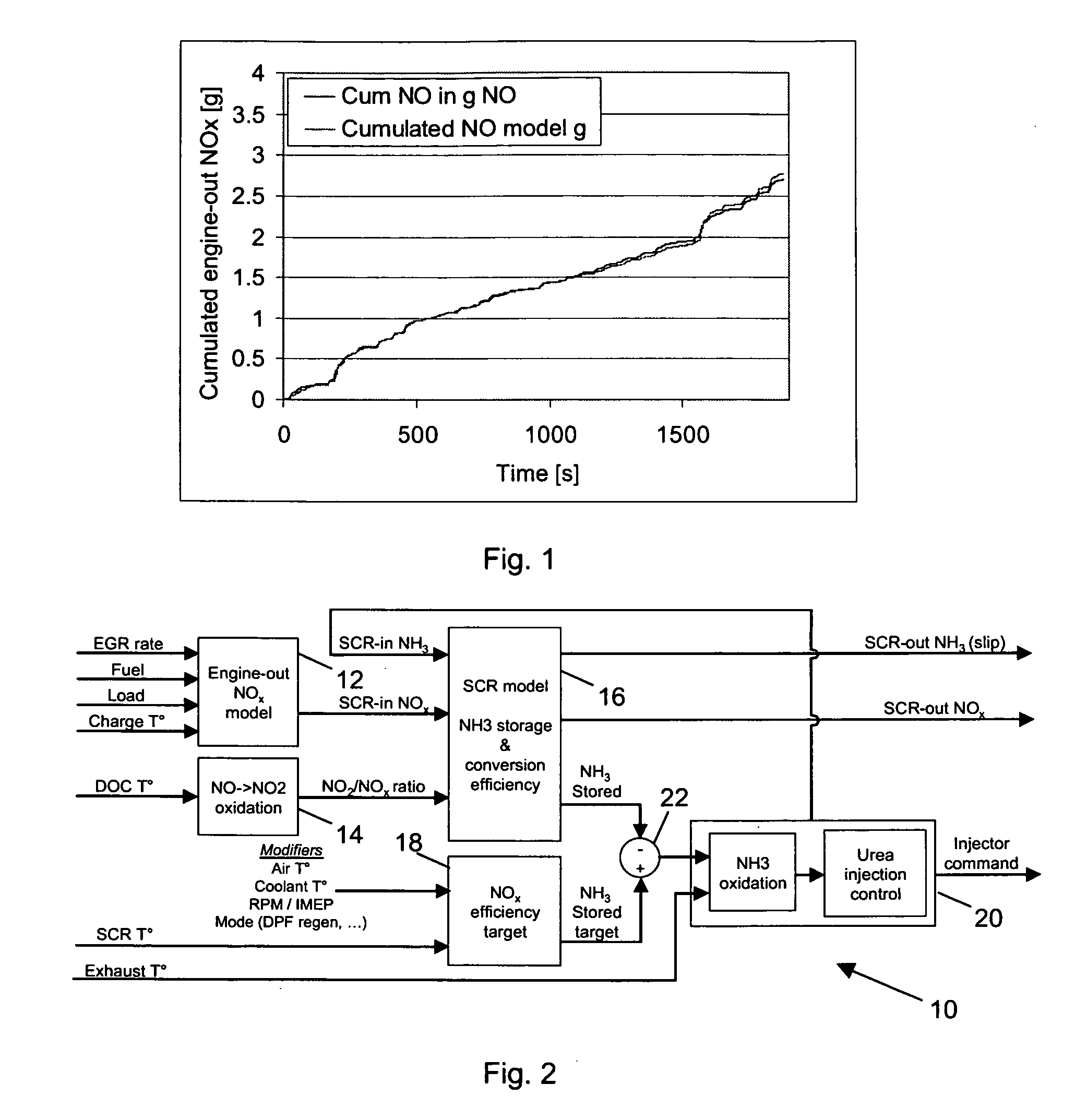
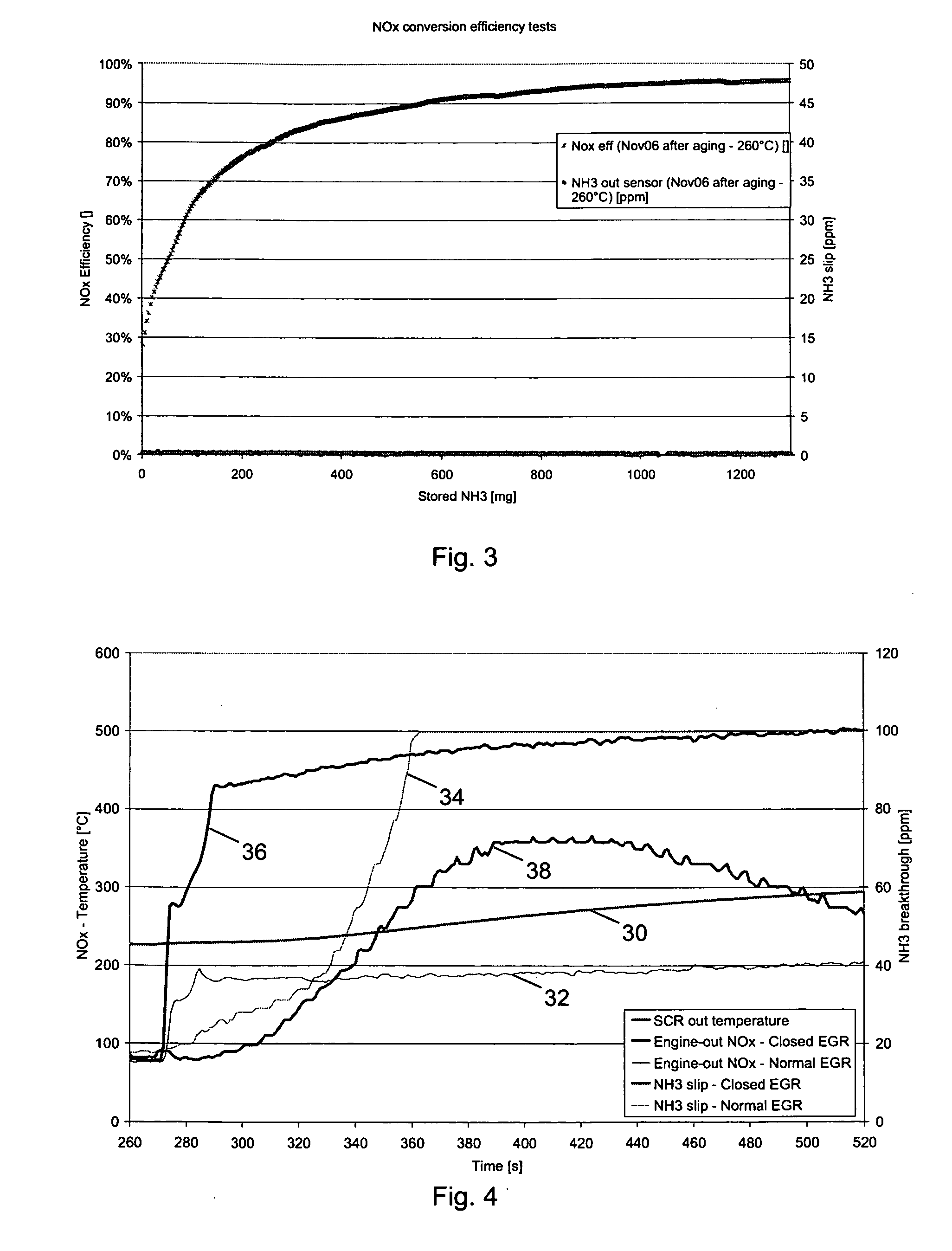
[0048]As explained above, the engine-out NOx flow needs to be known to inject the correct amount of urea, as too little gives poor efficiency and too much gives NH3 slip. Prior art systems use a NOx sensor located upstream of the SCR catalyst.

[0049]The present invention uses simplified models to calculate the NOx conversion efficiency of the SCR catalyst and drive the injection quantity of urea required to maintain this efficiency to a certain level. The model can take into account several key parameters including:

[0050]total NOx flow entering the SCR catalyst and NO2 / NOx ratio;

[0051]SCR catalyst temperature; and

[0052]stored NH3 in the SCR catalyst.

[0053]The total NOx flow can be measured by a NOx sensor located before the SCR.

[0054]Alternatively, as used in a preferable embodiment on the present invention, a NOx model can be used that replaces the NOx sensor. The NOx flow is modelled as a fraction of injected fuel flow. This fraction is mapped as a function of engine load (IMEP—Ind...


PUM


Abstract

A selective catalytic reduction (SCR) catalyst control system and method for an engine is disclosed. Urea injection to an SCR catalyst is determined based on an SCR catalyst model, which determines a value of stored NH3 in the SCR catalyst based on the NOx engine emission value, the SCR catalyst temperature, the quantity of urea supplied to the SCR catalyst and a pre-determined efficiency of conversion of NOx gases. A target value of stored NH3 and the value of stored NH3 in the SCR catalyst is then used to determine a stored NH3 differential, which is then used to calculate urea injection.

Description

BACKGROUND OF THE INVENTION[0001]The present invention relates to control of Selective Catalytic Reduction (SCR) catalyst and particularly, but not exclusively, to control of an SCR catalyst in vehicle engines.[0002]Selective Catalytic Reduction (SCR) catalysts remove nitrogen oxides (NOx), often the most abundant and polluting component in exhaust gases, through a chemical reaction between the exhaust gases, a reducing agent, and a catalyst.[0003]The control of Selective Catalytic Reduction (SCR) catalysts consists of injecting an amount of reducing agent, typically urea, also known as carbamide ((NH2)2CO), which decomposes to ammonia (NH3) and carbon dioxide in the presence of water, oxygen and heat. Ammonia then reacts with NOx gases to produce nitrogen and water. The amount of reducing agent injected is required to provide the maximum NOx conversion efficiency whilst keeping excess NH3, also known as NH3 slip, to low values. SCR catalysts have mainly been introduced on heavy dut...

Claims


Application Information

Patent Timeline
IPC IPC(8): F01N3/20
CPCF01N3/208F01N2560/026F01N2900/0411F01N2900/1402Y02T10/24F01N2900/1616F01N2900/1621F01N2900/1622F01N2900/1602Y02T10/12
Inventor PARMENTIER, MICHAELSCHMITT, JULIEN
Owner DELPHI INT OPERATIONS LUXEMBOURG S A R L
Learn More