Exhaust emission purifying apparatus for engine

a technology of exhaust gas purification apparatus and exhaust gas, which is applied in the direction of machines/engines, separation processes, transportation and packaging, etc., can solve the problems of reducing the purification efficiency of exhaust gas, insufficient mixing of reducing agent and exhaust gas, etc., and achieves the effect of easy production of fins, easy generation of swirling flow, and increased efficiency of purification of exhaust gas in the reduction catalytic converter

Active Publication Date: 2007-05-10
TOKYO ROKI +2
View PDF7 Cites 107 Cited by
  • Summary
  • Abstract
  • Description
  • Claims
  • Application Information

AI Technical Summary

Benefits of technology

[0021] According to a further embodiment of the apparatus of the first aspect, it is possible to easily produce the fins. In particular, the apparatus in which the fins are formed in the gasket, it is possible to easily generate the swirling flow in the exhaust gas only by modifying the gasket.
[0022] According to a still further embodiment of the apparatus in which the exhaust passage is formed such that an edge portion thereof is expanded in a bell-mouth shape, the exhaust gas in which the swirl-flow is generated, flows into the reduction catalytic converter formed with the diameter larger than that of the cross section of the exhaust passage on the exhaust upstream side, while being diffused along the inner peripheral face of the exhaust passage whose diameter is expanded in the bell-mouth shape. As a result, since the exhaust gas is rapidly diffused and flows into the reduction catalytic converter substantially uniformly, efficiency in purifying the exhaust gas in the reduction catalytic converter can be increased.
[0023] According to a further embodiment of the apparatus in which the reduction catalytic converter is formed to have a diameter thereof larger than that of the cross section of the exhaust passage on the exhaust upstream side thereof, and the exhaust passage is formed such that at least a part thereof between the injection nozzle and the reduction catalytic converter has the diameter expanded to form a substantially tapered shape toward the exhaust downstream side, the exhaust gas in which the swirling flow is generated, is diffused outward in a radial direction of the exhaust passage while being swirled along the inner peripheral face of the exhaust passage, when passing through the exhaust passage formed such that at least the part thereof between the injection nozzle and the reduction catalytic converter has the diameter expanded to form the substantially tapered shape. As a result, since the exhaust gas is sufficiently diffused in the exhaust passage and allowed to flow into the reduction catalytic converter substantially uniformly, it is able to enhance efficiency in purifying the exhaust gas in the reduction catalytic converter.
[0024] According to the exhaust emission purifying apparatus of the second aspect, the swirl-flow generating means is formed on the center portion of the partition plate disposed on the exhaust upstream side of the injection nozzle to traverse the exhaust passage, to thereby generate the swirling flow of the exhaust gas which spirally swirls. Further, the discharge holes are formed in

Problems solved by technology

However, in the above conventional exhaust emission purifying apparatus, there might be a possibility that the mixing of the reducing agent with the exhaust gas is insufficient, when injection of the reducing agent is carried out at a position located on the exhaust upstream side of the NOx reduction c

Method used


Image

  • Exhaust emission purifying apparatus for engine
  • Exhaust emission purifying apparatus for engine
  • Exhaust emission purifying apparatus for engine

Examples


Embodiment Construction

[0040] Hereunder, there will be described embodiments of the present invention based on the accompanying drawings.

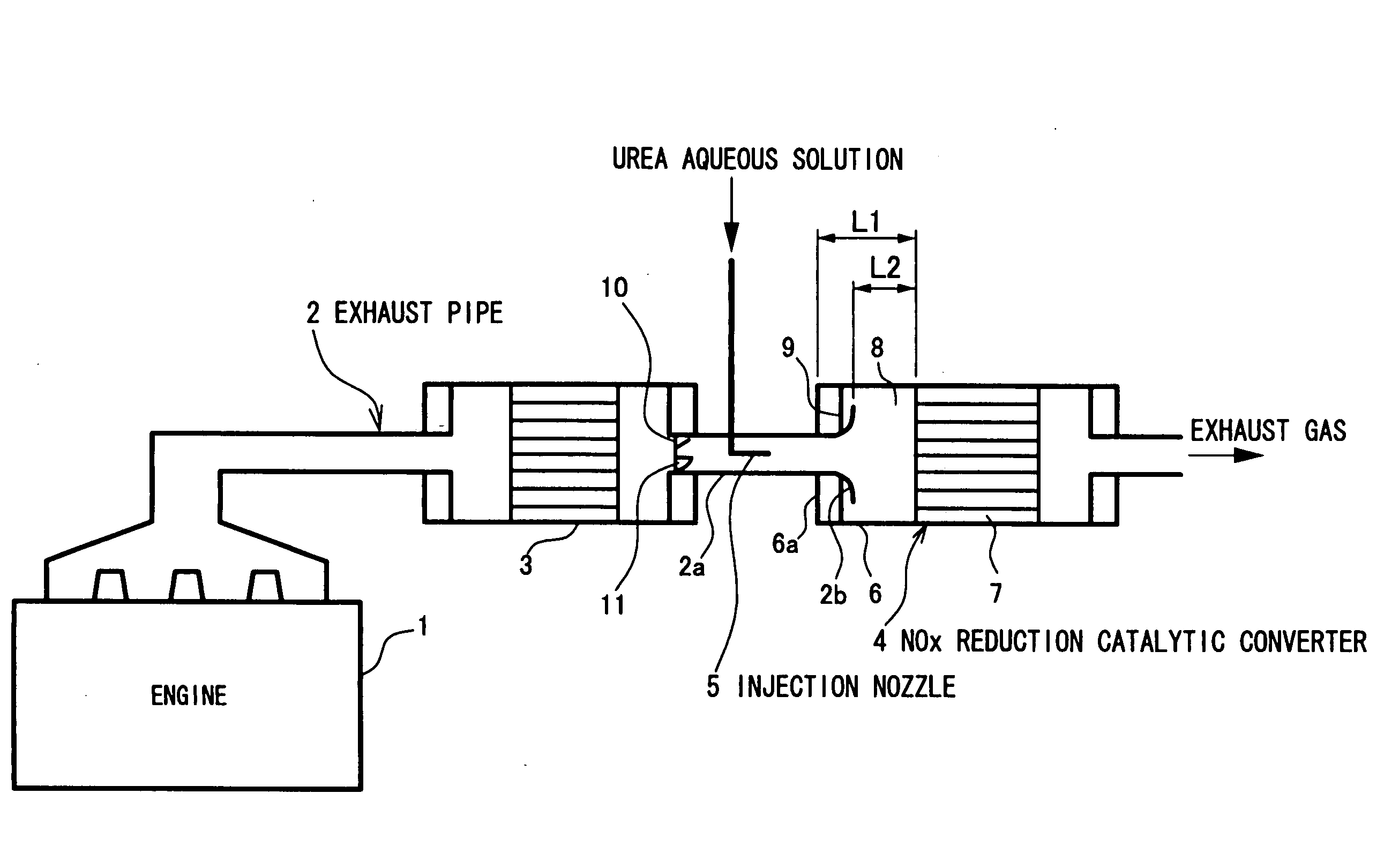
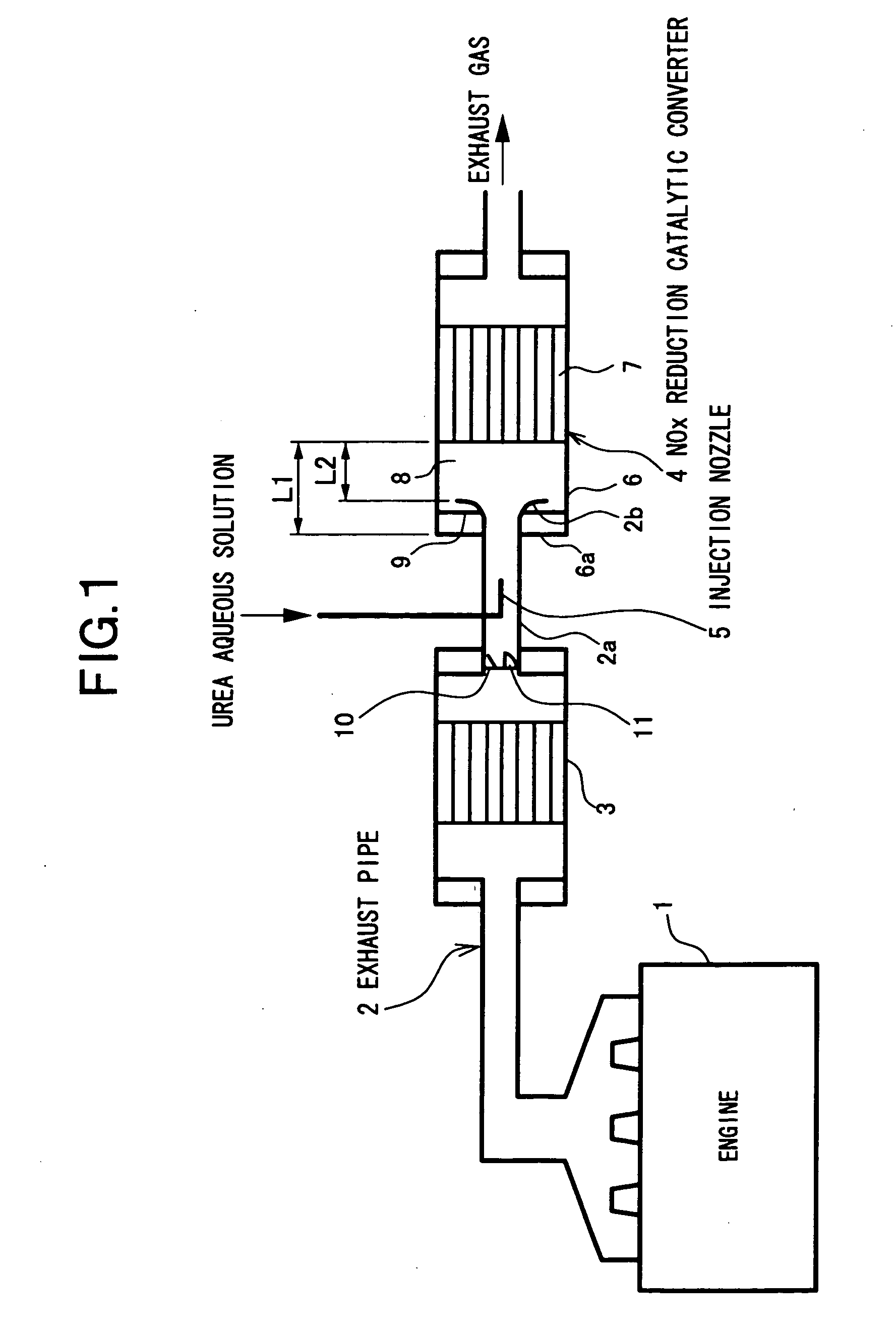
[0041]FIG. 1 is a schematic configuration diagram showing a first embodiment of an exhaust emission purifying apparatus for an engine according to a first aspect of the present invention. This exhaust emission purifying apparatus is for reductively eliminating nitrogen oxides (NOx) in the exhaust gas by using a reducing agent, and comprises: a reduction catalytic converter disposed in an exhaust passage of the engine, for reductively purifying nitrogen oxides in the exhaust gas with the reducing agent; an injection nozzle for injection-supplying the reducing agent to an exhaust upstream side of the reduction catalytic converter in the exhaust passage; and swirl-flow generating means disposed on an exhaust upstream side of an injection position of the reducing agent injected from the injection nozzle, for generating the swirling flow of the exhaust gas which spirally swi...


PUM

PropertyMeasurementUnit
Angleaaaaaaaaaa
Flow rateaaaaaaaaaa
Diameteraaaaaaaaaa

Abstract

An exhaust emission purifying apparatus has a NOx reduction catalytic converter in an exhaust passage of an engine, for purifying nitrogen oxides in the exhaust gas by reduction with urea aqueous solution; an injection nozzle injecting the urea solution toward an exhaust upstream side of the converter in the exhaust passage; and fins disposed on an exhaust upstream side of an injection position of the urea solution in the injection nozzle, for generating a spiral swirling flow of the gas swirling about a center corresponding to the central axis of an exhaust pipe. The swirling flow generated in the exhaust gas prior to the injection-supply of the urea aqueous solution promotes mixing of the solution with the gas to thereby promote the hydrolysis of the urea solution. And the exhaust gas and ammonia generated from the urea solution are uniformly mixed together.

Description

[0001] This application is a continuation of PCT / JP2005 / 012994, filed on Jul. 14, 2005.BACKGROUND OF THE INVENTION [0002] 1. Field of the Invention [0003] The present invention relates to an exhaust emission purifying apparatus for purifying an exhaust gas from an engine by eliminating nitrogen oxides (NOx) in the exhaust gas by reduction using a reducing agent, and in particular, to an exhaust emission purifying apparatus for an engine, that is provided with a swirling flow generating means disposed in an exhaust passage for generating a swirling flow of the exhaust gas in order to increase efficiency in purifying of the exhaust gas. [0004] 2. Description of the Related Art [0005] As a catalytic purifying system of eliminating NOx contained in the exhaust gas of an engine, there has conventionally been proposed an exhaust emission purifying apparatus. In such a conventional exhaust emission purifying apparatus, a NOx reduction catalytic converter is disposed in an exhaust passage o...

Claims


Application Information

Patent Timeline
IPC IPC(8): F01N3/00F01N13/08
CPCB01D53/9431B01D2251/2067B01F3/04049B01F5/0451B01F5/0616B01F5/0646B01F5/0653F01N3/206F01N3/2066F01N3/2892F01N2240/20F01N2570/14F01N2610/02Y02T10/24F01N13/009Y02A50/20Y02T10/12B01F23/2132B01F25/3131B01F25/4315B01F25/4336B01F25/433
Inventor KANAYA, ISAMUHONDA, KOUTAROUAMEMIYA, TOMOKOHIRATA, KIMINOBUMASAKI, NOBUHIKOOBANA, SHINYASHIRAI, DAISUKEHIRAMOTO, HITOSHIYAMADA, NAOBUMI
Owner TOKYO ROKI
Why Eureka
Try Eureka