Oil Filter Wrench

Active Publication Date: 2010-03-04
LISLE CORPORATION
View PDF9 Cites 2 Cited by
  • Summary
  • Abstract
  • Description
  • Claims
  • Application Information

AI Technical Summary

Benefits of technology

[0006]Briefly, the present invention comprises a flexible band, canister wrench wherein the inside surface of the band includes a patterned layer of abrasive, fused metal. The fused metal is applied in a manner that provides a wear resistant, abrasive surface pattern on the inside surface of the band that signific

Problems solved by technology

Thus, when the oil filter wrench becomes contaminated w

Method used


Image

  • Oil Filter Wrench
  • Oil Filter Wrench
  • Oil Filter Wrench

Examples


Example

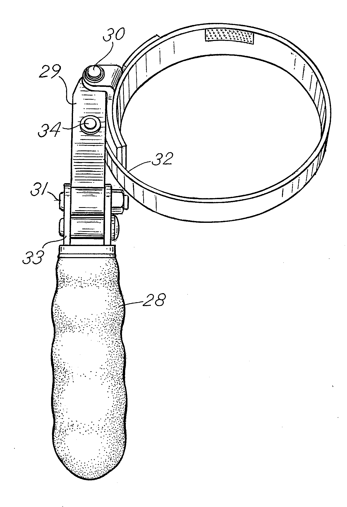
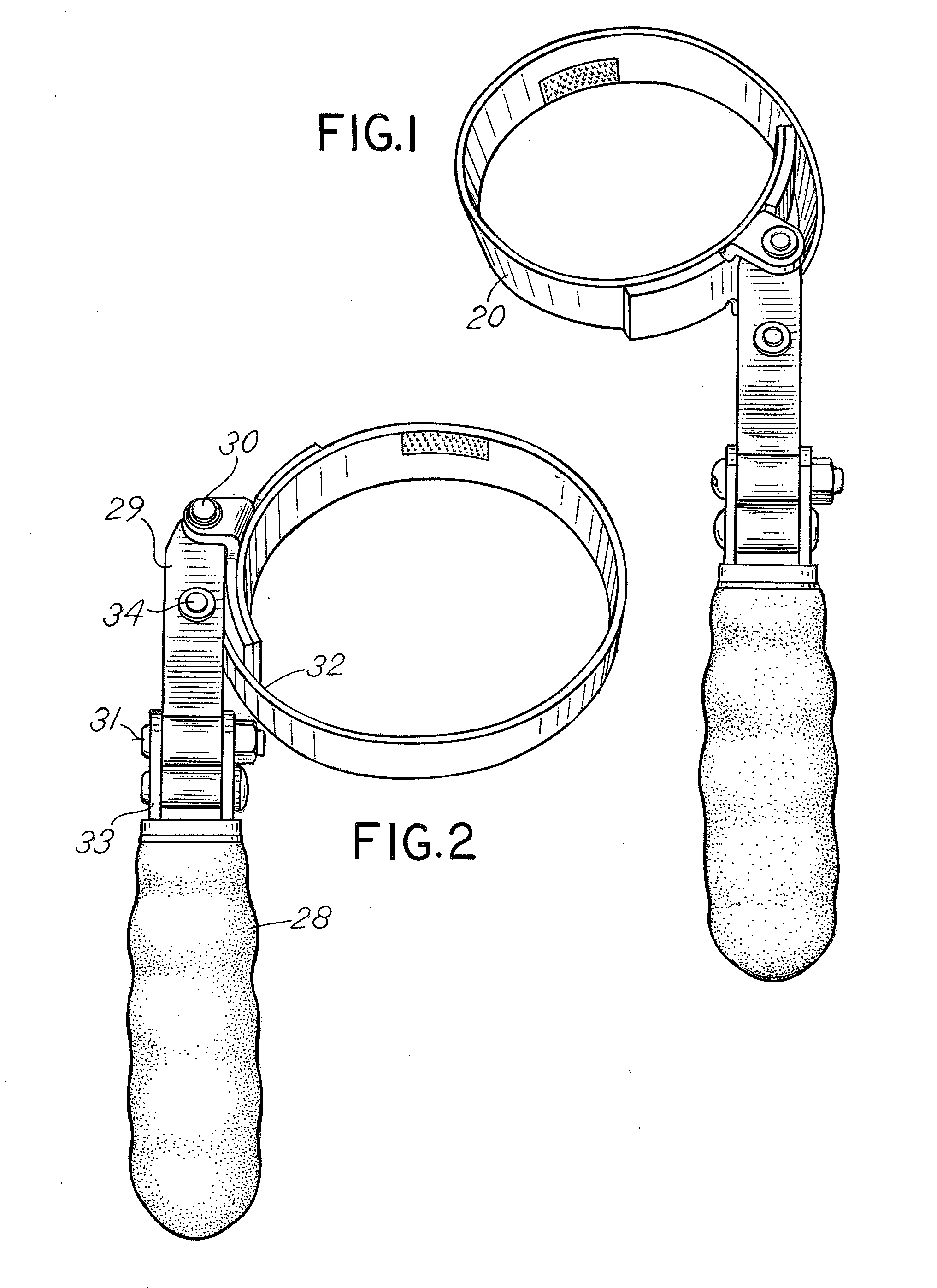
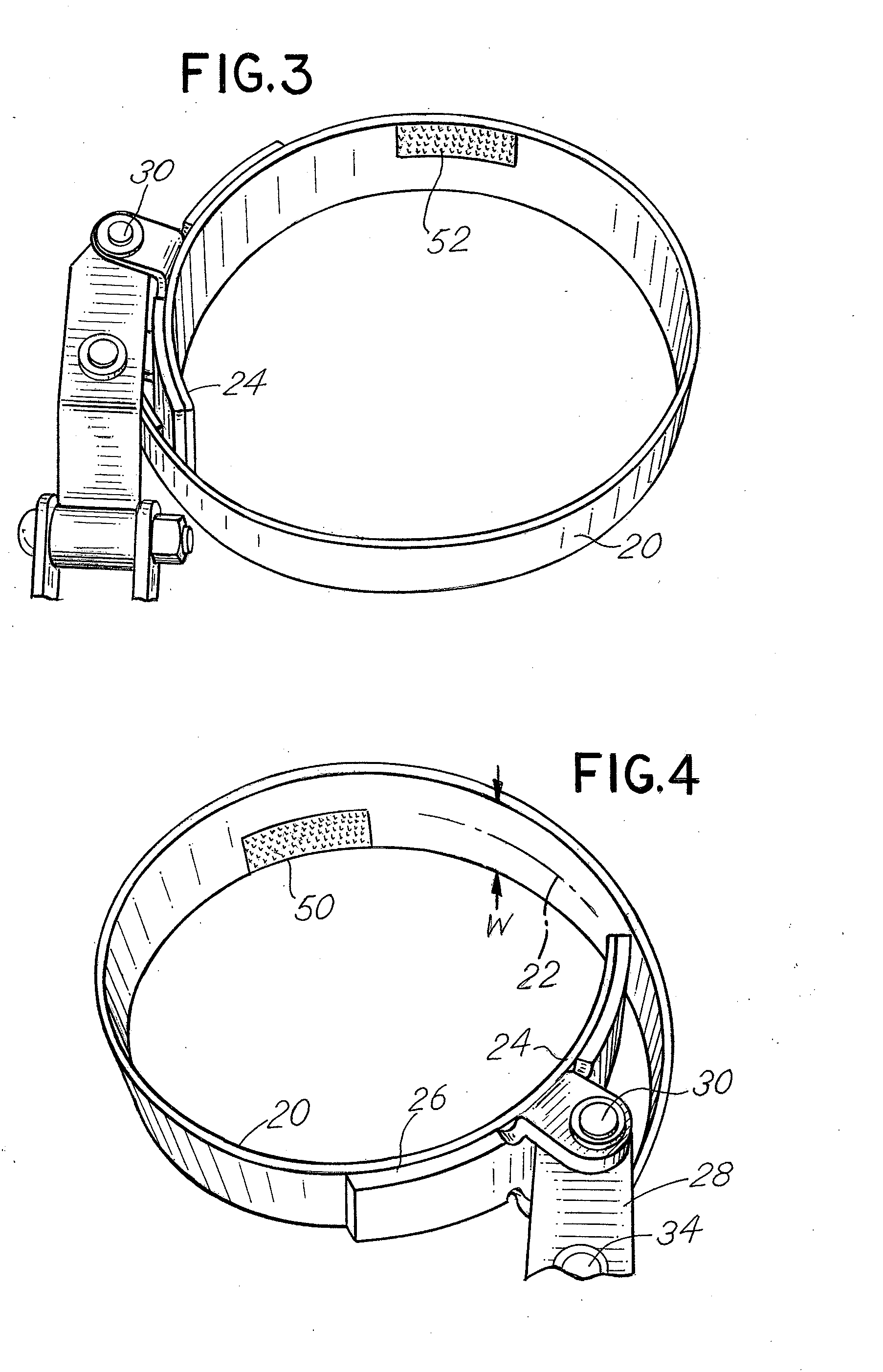
[0030]Referring to the figures, the embodiment depicted in FIGS. 1-4 comprises a metallic band 20 which is generally circular and includes a width dimension in FIG. 4 represented by the width W and a longitudinal axis 22 along the elongate dimension. The band 20 terminates at one end or a first end 24 where it is attached to a bracket 26 associated with a lever arm 28 for pivoting about a first pivot connection 30. The opposite end or second end 32 of the band 20 is attached to a second pivot 34 of the lever arm 28.

[0031]The lever arm 28 is comprised of a bracket member 29 which is attached by a pivot bolt 31 to a handle member 33. Handle member 33 may thus pivot about the axis of bolt 31. The handle member 33 is a molded, elongate member designed for manual gripping and for pivoting about the axis of the bolt 31 in order to position the oil filter wrench in a desired manner for removal or installation of a canister. As depicted in FIGS. 9 and 10, the lever arm 28 and, more particul...


PUM


Abstract

An oil filter wrench includes a flexible stainless steel band having a pattern of sputtered alloy material coating at least part of the inside surface of the band to enhance the gripping ability of the oil filter wrench as the band is tightened above the outside surface of a cylindrical canister during removal or installation of the oil filter canister.

Description

CROSS REFERENCE TO RELATED APPLICATIONS[0001]This is a utility application incorporating by reference, claiming priority to and derived from the following provisional applications: (1) Application Ser. No. 61 / 092,611, filed Aug. 28, 2008, entitled “Oil Filter Wrench” and (2) Application Ser. No. 61 / 184,325, filed Jun. 5, 2009, entitled “Oil Filter Wrench”.BACKGROUND OF THE INVENTION[0002]In a principal aspect the present invention relates to an oil filter wrench, or wrench of similar purpose, useful for engaging and turning cylindrical bodies, such as an oil filter canister.[0003]When servicing motor vehicles, and, in particular, motor vehicle engines, a typical task is the replacement of the oil filter canister which usually has a cylindrical shape. There are various patents which disclose tools for removal and replacement of such oil filter canisters. By way of example, U.S. Pat. No. 5,388,485 discloses a typical oil filter wrench construction. Similarly, U.S. Pat. No. 5,090,274 d...

Claims


Application Information

Patent Timeline
IPC IPC(8): B25B13/52B25B23/16B25B23/00
CPCB25B27/0042
Inventor PULLEN, GARY L.
Owner LISLE CORPORATION
Why Eureka
Try Eureka