Angle indicating device for table saw

a technology of indicating device and table saw, which is applied in the field of table saw, can solve the problems of user difficulty in easily and precisely operating the saw blade of the typical woodworking machine, user difficulty in knowing the angular position, and the user's inability to precisely read the angular position of the saw blade relative to the supporting base, so as to achieve the effect of easy and precise operation of the saw blad

Inactive Publication Date: 2010-03-04
YU BEN
View PDF12 Cites 15 Cited by
  • Summary
  • Abstract
  • Description
  • Claims
  • Application Information

AI Technical Summary

Benefits of technology

[0012]The primary objective of the present invention is to provide a table saw including an angle indicating device for precisely indicating the tilting angle of the saw blade relative to the supporting base and for allowing the user to easily and precisely operate the saw blade of the table saw.
[0013]In accordance with one aspect of the invention, there is provided a table saw comprising a supporting base including a chamber formed therein, and including a curved channel formed therein and communicating with the chamber of the supporting base, a cradle pivotally attached to the supporting base, and including a bevel sector gear having a rack provided on the bevel sector gear of the cradle, an arbor bracket pivotally attached to the cradle with a pivot rod for allowing the arbor bracket to be pivoted relative to the cradle, and including a bevel sector gear having a rack provided on the bevel sector gear of the arbor bracket, a height shaft rotatably attached to the cradle and extended out through the curved channel of the supporting base, and including a worm engaged with the rack of the bevel sector gear of the arbor bracket for pivoting the bevel sector gear and the arbor bracket relative to the cradle and the supporting base, a saw blade rotatably attached to the arbor bracket with an axle, a motor attached to the arbor bracket and coupled to the axle of the saw blade for rotating the saw blade, a tilt shaft rotatably attached to the supporting base and including a worm engaged with the rack of the bevel sector gear of the cradle for pivoting the bevel sector gear of the cradle and the arbor bracket relative to the supporting base 10 and for adjusting the saw blade relative to the supporting base to selected angular positions, a follower slidably engaged in the curved channel of the supporting base moveable along the curved channel of the supporting base with the height shaft, and a signal generating device attached to the follower for detecting a relative position between the height shaft and the follower and for detecting a bevel angle of the arbor bracket and the cradle and the saw blade relative to the supporting base and for allowing the user to easily and precisely operate the saw blade of the table saw.

Problems solved by technology

However, the typical woodworking machine has no angle indicating devices to indicate the tilting angle of the saw blade relative to the supporting base such that the user may not easily know the angular positions of the saw blade relative to the supporting base and such that the user may not easily and precisely operate the saw blade of the typical woodworking machine.
However, the angular positions of the saw blade relative to the supporting base may not be precisely read the user unless the user is precisely stood in front of the bevel pointer and the scale, and the angular positions of the saw blade relative to the supporting base may only be roughly estimated by reading the digit or graduation provided on the scale.
However, similarly, the typical table saws also have no angle indicating devices to indicate the tilting angle of the saw blade relative to the supporting base such that the user may not easily know the angular positions of the saw blade relative to the supporting base and such that the user may not easily and precisely operate the saw blade of the table saw.

Method used


Image

  • Angle indicating device for table saw
  • Angle indicating device for table saw
  • Angle indicating device for table saw

Examples


Embodiment Construction

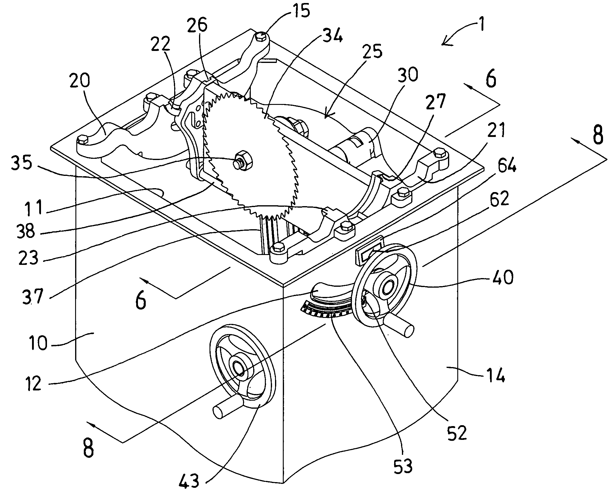
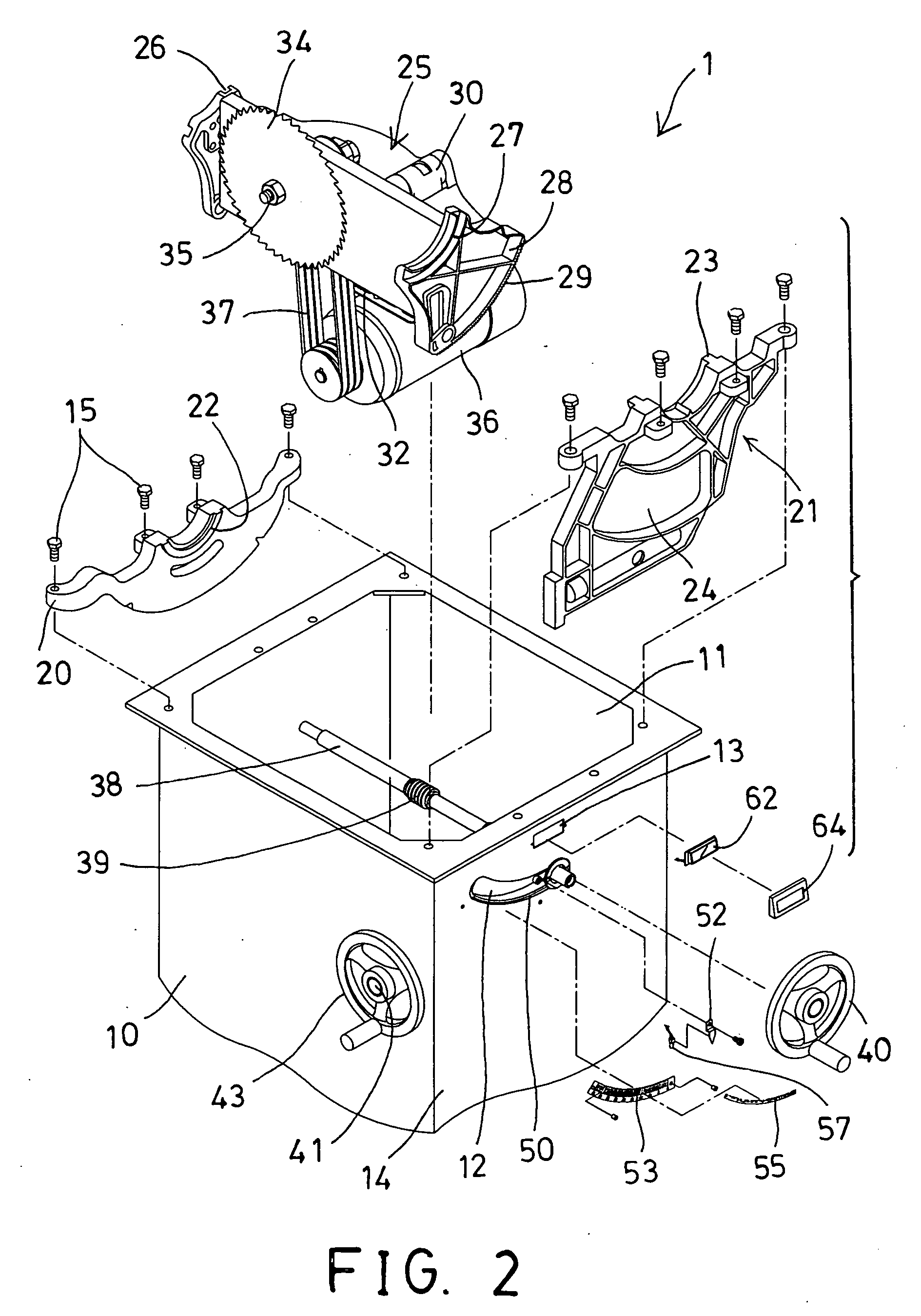
[0036]Referring to the drawings, and initially to FIGS. 1-6, a table saw 1 in accordance with the present invention comprises an outer housing or supporting base 10 including a chamber 11 formed therein, and including a curved channel 12 and an orifice 13 (FIG. 2) formed in one of four side walls 14 of the supporting base 10 and communicating with the chamber 11 of the supporting base 10, and comprises two trunnion brackets 20, 21 engaged into the chamber 11 of the supporting base 10 and attached or secured or mounted to the supporting base 10 with latches or fasteners 15 for rotatably or pivotally supporting a cradle 25, the trunnion brackets 20, 21 each include a curved grooves or rails or tracks 22, 23 formed or provided thereon, and one of the trunnion brackets 21 includes an opening 24 formed therein (FIG. 2) and aligned with or communicating with the curved channel 12 of the supporting base 10.

[0037]The cradle 25 includes two curved rails or grooves or tracks 26, 27 formed or ...


PUM

PropertyMeasurementUnit
heightaaaaaaaaaa
bevel angleaaaaaaaaaa
tilting angleaaaaaaaaaa

Abstract

A table saw includes a curved channel formed in a supporting base, a cradle attached to the supporting base, an arbor bracket attached to the cradle for supporting a saw blade and a motor, a height shaft attached to the cradle and extended through the curved channel of the base for engaging with the arbor bracket, a tilt shaft attached to the base and engaged with the cradle for adjusting the saw blade relative to the base to selected angular positions, a follower slidably engaged in the curved channel of the base, and a signal generating device attached to the follower for detecting a bevel angle of the arbor bracket and the cradle and the saw blade relative to the base and for precisely showing the angle with digits.

Description

BACKGROUND OF THE INVENTION[0001]1. Field of the Invention[0002]The present invention relates to a table saw or a woodworking machine, and more particularly to a table saw including an angle indicating device for precisely indicating the tilting angle of the saw blade relative to the supporting base and for allowing the user to easily and precisely operate the saw blade of the table saw.[0003]2. Description of the Prior Art[0004]Typical table saws comprise a saw blade rotatably supported in a supporting base, and a rotatable elevation wheel and a tilt wheel attached to the supporting base and coupled to the saw blade for adjusting the saw blade relative to the supporting base to any selected or predetermined angular positions in order to suitably cut or machine the work pieces.[0005]For example, U.S. Pat. No. 5,024,257 to Lloyd discloses one of the typical woodworking machines which also comprise a rotatable elevation wheel and a tilt wheel attached to the supporting base and couple...

Claims


Application Information

Patent Timeline
Patent Type & Authority Applications(United States)
IPC IPC(8): B23Q16/00B26D1/14B26D7/27B26D7/00
CPCB23D59/002Y10T83/85Y10T83/853Y10T83/7788Y10T83/7705Y10T83/7697Y10T83/773
Inventor YU, BEN
Owner YU BEN
Why Eureka
Try Eureka