Modular data center

a data center and module technology, applied in the field of modules, can solve the problems of data center construction, data center availability, and time-consuming, and achieve the effects of convenient movement, less expense, and rapid operation

Inactive Publication Date: 2010-03-04
CES GRP
View PDF10 Cites 78 Cited by
  • Summary
  • Abstract
  • Description
  • Claims
  • Application Information

AI Technical Summary

Benefits of technology

[0002]The subject invention over comes this problem by providing a modular data center which contains all of the necessary infrastructure and can be built off-site in a factory and delivered to its desired location and become operational quickly and at less expense than building a data center from scratch on site. In addition, it can later be easily moved to a different location. This is accomplished with a unitary rack having multiple side-by-side bays configured to carry electronic components. The rack has a first passageway which provides access to the front side of the bays and a second passageway on the back side of the bays. A plurality of fans associated with the rack circulate cool air vertically through either the first or second passageway and then horizontally through the bays to cool the components mounted in the bays. In a preferred embodiment, the rack and fans can be inserted as a unit into a trailer or a container or walls can be built around the rack, either of which allows the entire data center to be easily moved.

Problems solved by technology

Constructing a data center of any complexity takes considerable time and incurs considerable expense.
And yet, data centers often must be provided on short notice.
When this occurs, the data center is out of use while it is being disassembled and reassembled at considerable expense.

Method used


Image

  • Modular data center
  • Modular data center
  • Modular data center

Examples


Embodiment Construction

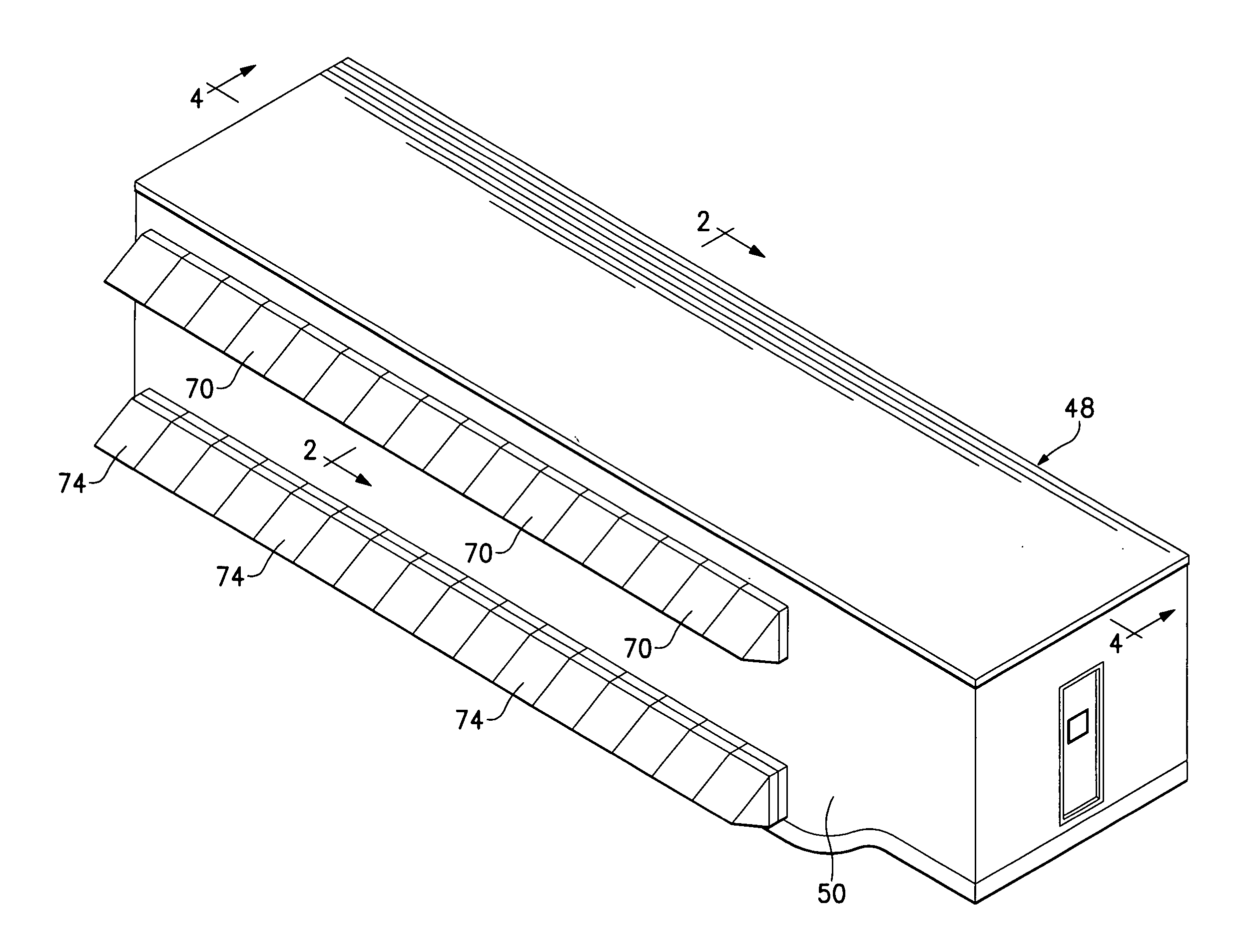
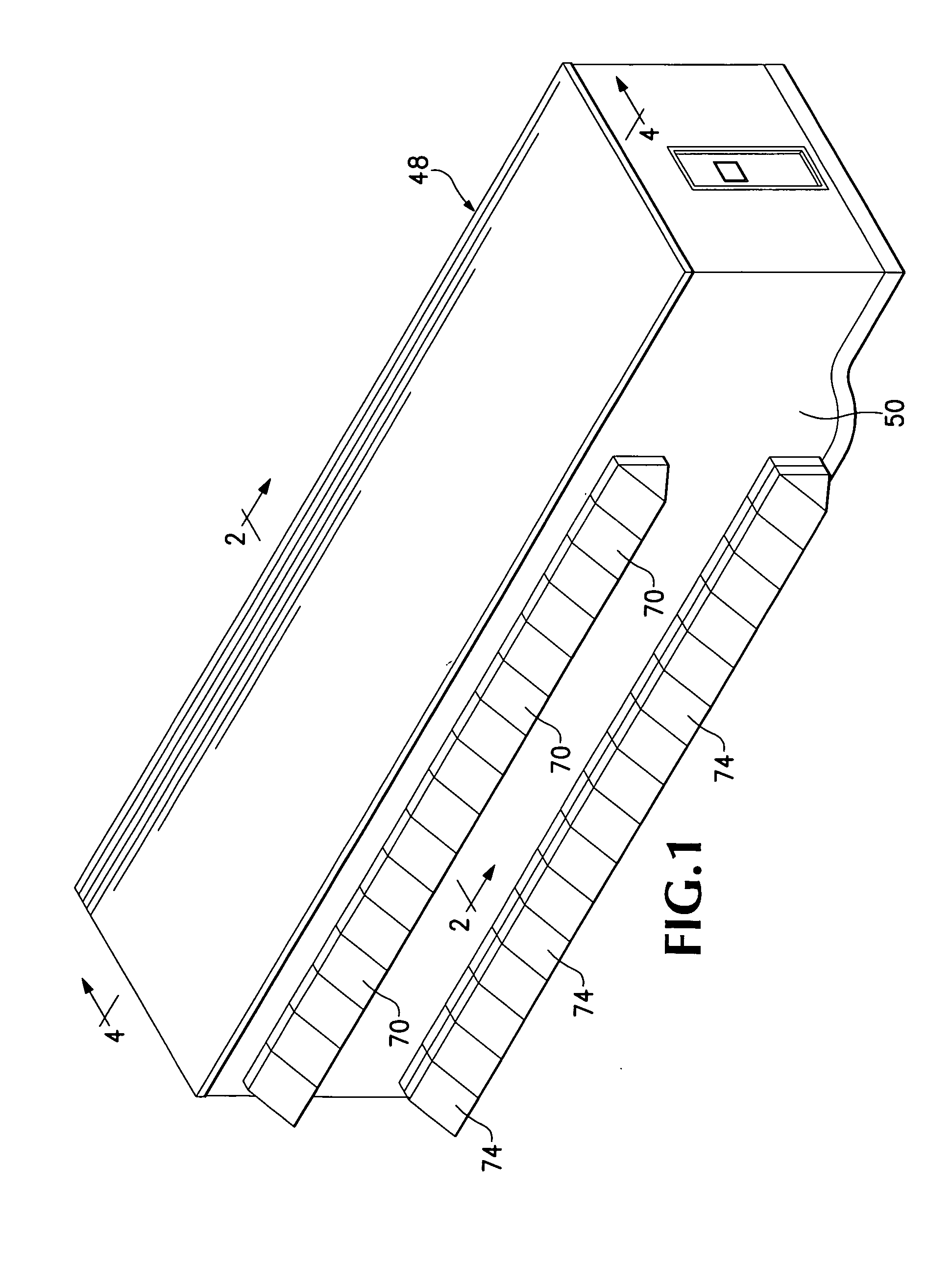
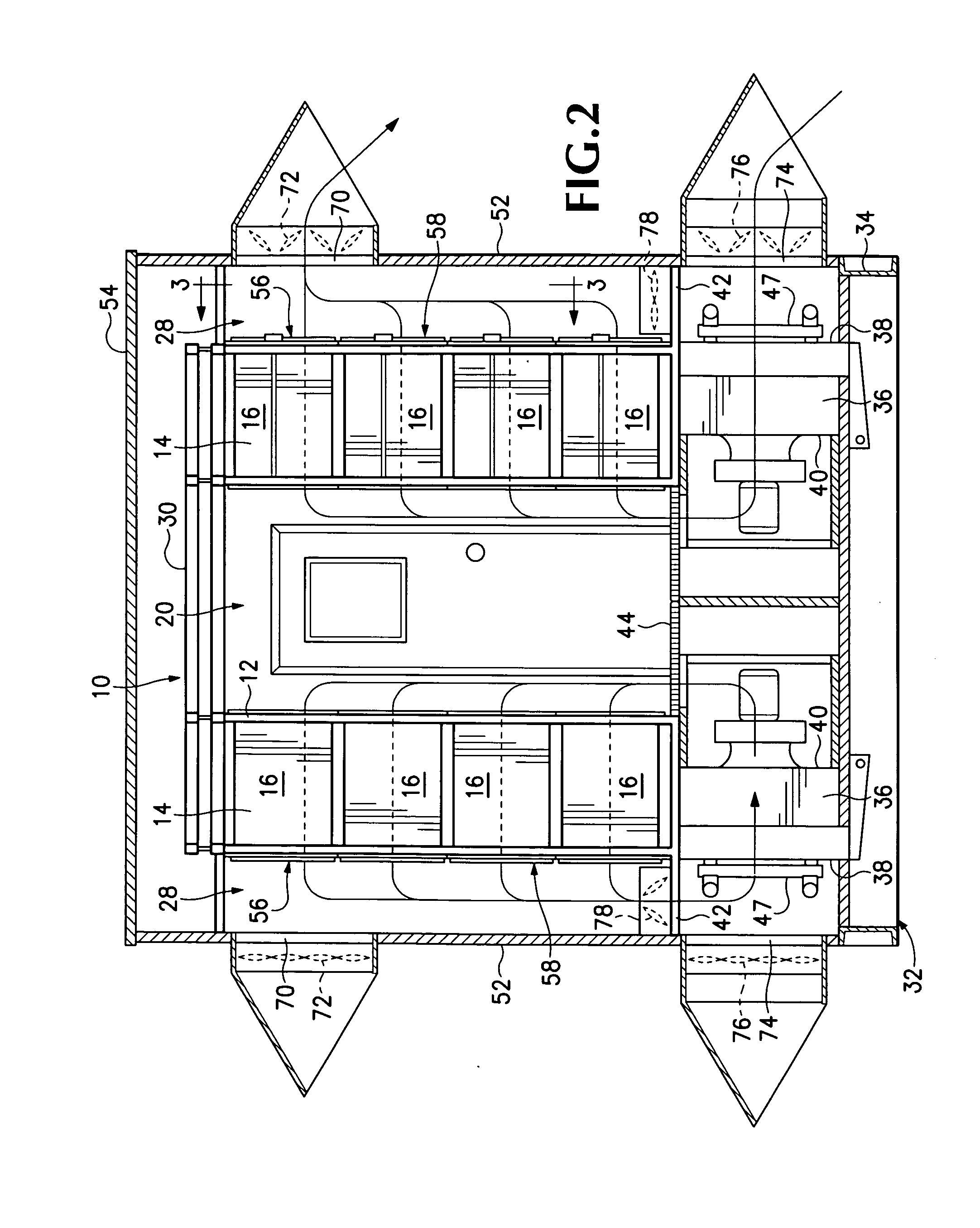
[0009]Referring to FIGS. 2 and 5 of the drawings, a mobile data center includes a rack 10 which is a unitary structure preferably made from metal tubing 12. The rack has a width “W”, a height “H” and length “L”. In the embodiment illustrated, the rack contains two rows of side-by-side bays 14 which are sized to carry multiple electronic component chassis 16 each of which is capable of carrying multiple electronic components 18. The rows of bays are separated from one another by a first passageway 20 which is defined by the front side 22 of the bays 14. The chassis 16 are inserted into the bays and the electronic components are inserted into the chassis from the front sides 22 and the electronic components 18 are accessed from the passageway. In order to accommodate this, the passageway has a width which allows a person to walk through it. A series of holes 24 are located at appropriate intervals in the front sides of the tubing 12 in order to allow the chassis to be bolted to the ra...


PUM


Abstract

A modular data center includes a unitary rack having multiple side-by-side bays which are arranged to carry electronic components. The rack has a first passageway on its front side which provides access to the electronic components mounted in the bays. The rack has a second passageway located adjacent to the back side of the bays. A plurality of fans circulate cooling air vertically in a first direction through either the first or second passageway and then horizontally through the bays. In the preferred embodiment, the air flows vertically in the opposite direction in the other passageway back to the fan to be cooled and recirculated. The rack and fans can either be inserted into a trailer or container or walls can be built around them to provide a modular unit.

Description

BACKGROUND OF THE INVENTION[0001]Many businesses have extensive computer and telecommunication equipment which needs to be readily accessible and have the components housed in a manner that allow them to be easily replaced. This is accomplished through a data center comprising a series of racks which are configured to carry multiple electronic components. The data center provides a systematic way to provide power to these components along with the wiring necessary to operate them. Because electronic components generate significant heat, the data center also provides cooling air at the required level for the components in the data center. Constructing a data center of any complexity takes considerable time and incurs considerable expense. And yet, data centers often must be provided on short notice. In addition, a data center may be required at a particular location for only a short period of time, after which it may be necessary to disassemble it and move it to a new location. When ...

Claims


Application Information

Patent Timeline
Patent Type & Authority Applications(United States)
IPC IPC(8): A47F7/00
CPCH05K7/1497H05K7/20745H05K7/20736
Inventor SCHREIBER, KEVIN
Owner CES GRP
Why Eureka
Try Eureka