Low profile derail

a low-profile, derailment technology, applied in the direction of rail engagement elements, interlocking points of signals, transportation and packaging, etc., to achieve the effect of improving the design of the derailment, and reducing the weight of the derailmen

Active Publication Date: 2010-03-04
WESTERN CULLEN HAYES
View PDF10 Cites 3 Cited by
  • Summary
  • Abstract
  • Description
  • Claims
  • Application Information

AI Technical Summary

Benefits of technology

[0008]There is a need in the railroad industry to provide a derail, preferably relatively light in weight, to be portable and yet be effective to derail an undesirably moving locomotive, having a weight of approximately 350,000 pounds or even two such locomotives, at about 950,000 pounds connected together, wherein the locomotive's pilot will clear the derail of the present invention used on the track without the derail being forced off by the pilot of the locomotive before the lead wheel reaches the derail. The derail must be less than three inches in height above the upper surface of the track, preferably providing a ¼″ clearance between the pilot and the derail, and yet be strong and sturdy enough to effectively derail 350,000 pounds of one locomotive or, possibly, even two connected locomotives moving at speeds up to 10 miles per hour.
[0009]The above-mentioned need for a portable derail sufficiently strong to derail one or two locomotives at speeds up to 10 miles per hour is accomplished by an improved derail design. The low profile derail (less than three inches in overall height clearance from the top of the rail) includes an elongated derail shoe in direct contact with and completely covering the entire length

Problems solved by technology

Apparent potential problem areas

Method used


Image

  • Low profile derail
  • Low profile derail
  • Low profile derail

Examples


embodiment 20

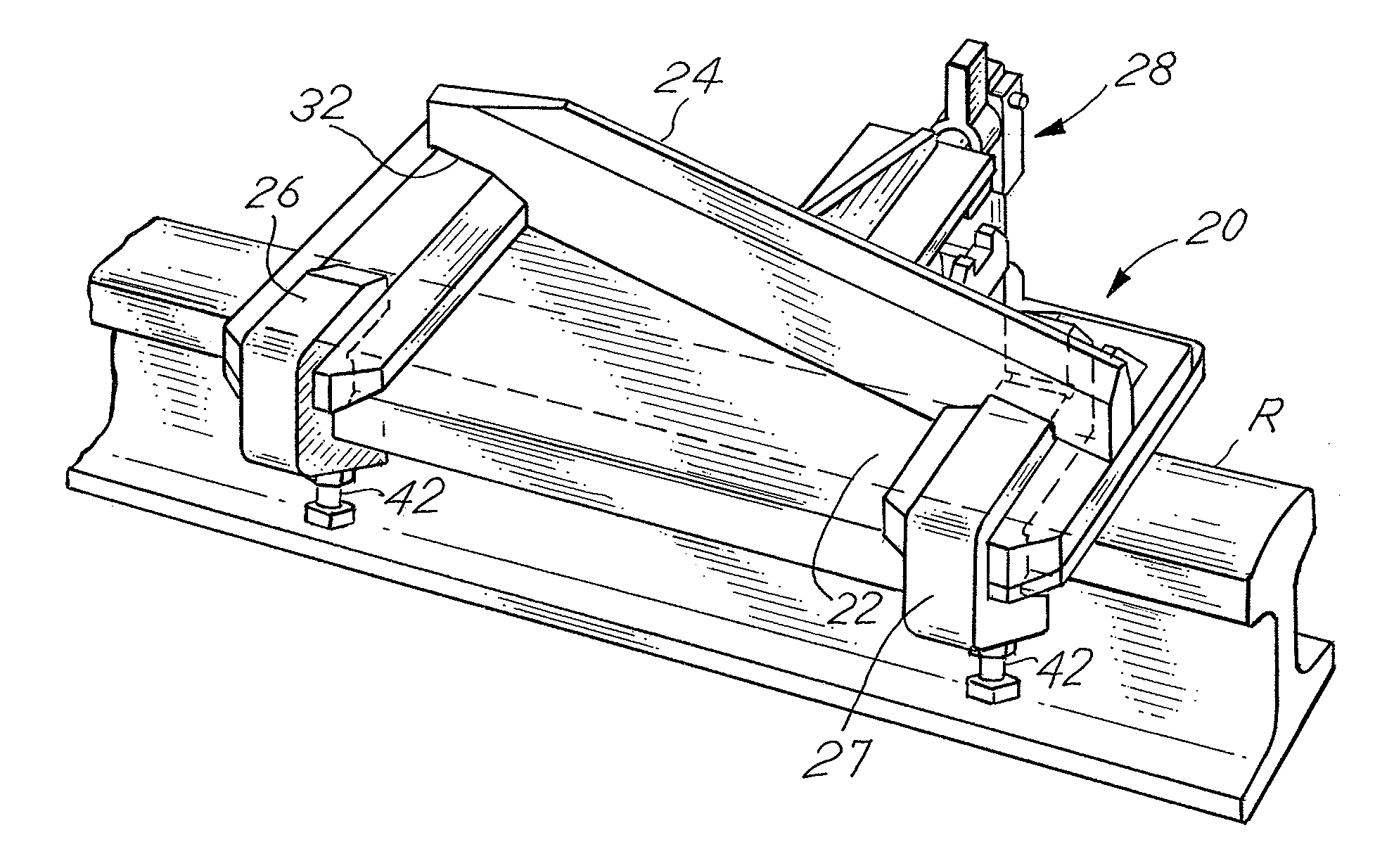
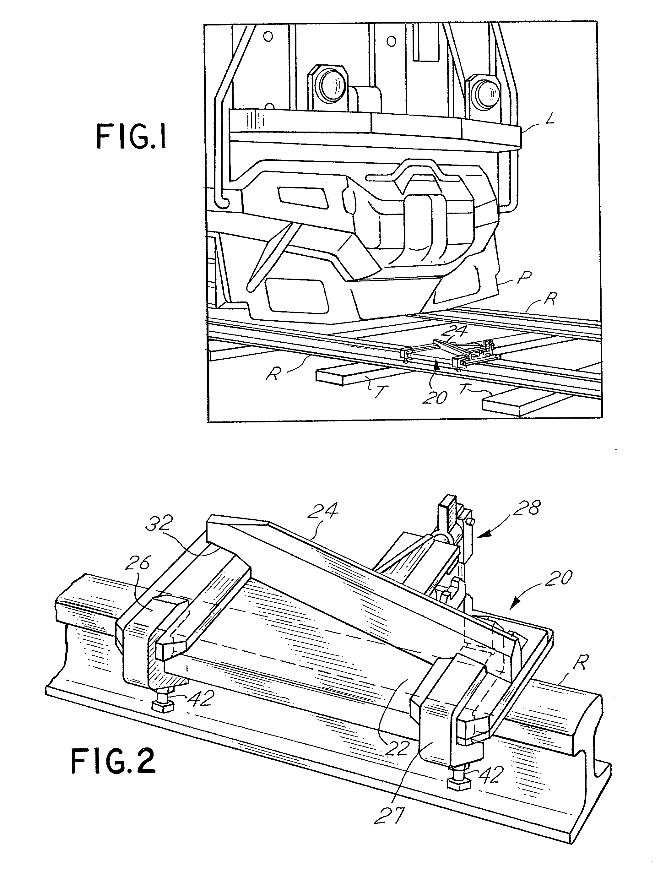
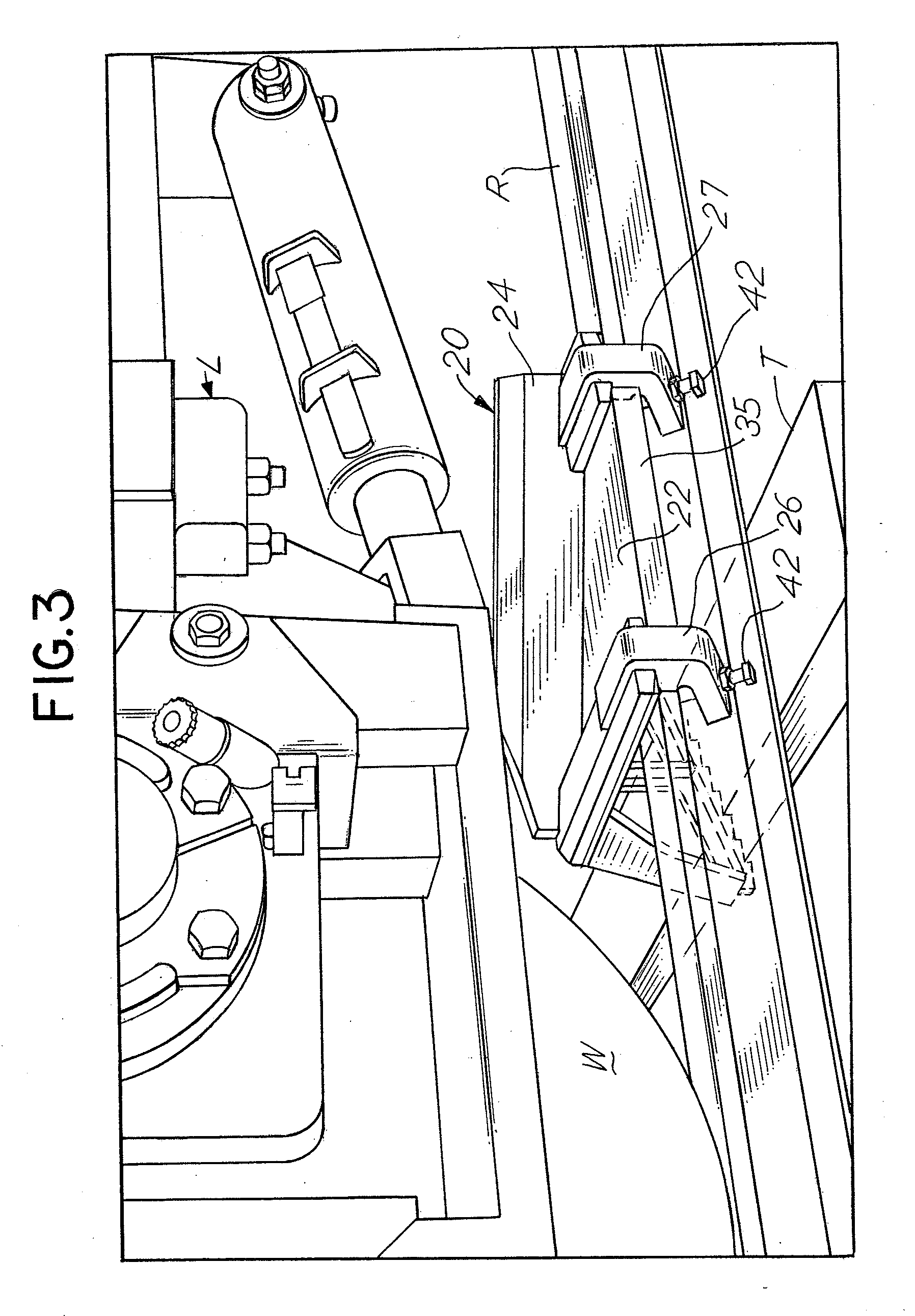
[0029]Referring to FIGS. 4-6, the derail embodiment 20 is shown in somewhat greater detail. Some common details are found in U.S. Pat. No. 6,105,906, which is incorporated herein by reference. As previously indicated, the upright deflecting bar 24 is effectively angled outwardly to engage the moving lead wheel W of the locomotive L since the pilot P of the locomotive L has cleared the highest point of the derail assembly 20, thereby derailing the moving locomotive L to the field side of the rail R.

[0030]Referring to FIGS. 4-6. the entrance derail hook 26 is rigidly secured to the derail shoe plate 22, as by welding, along its lower surface while the inner end or gage side end 32 of the entrance derail hook 26 is welded to the outer or field side face of the entrance end of the deflecting bar 24.

[0031]The derail shoe 22 is a rigid heavy duty plate that is welded to the lower edge of the upright deflecting bar 24 along the entire length of the bar 24 along the field side face of the d...

embodiment 48

[0036]The improved derail embodiment 48 is shown in FIGS. 7-11 which includes a derail shoe plate 50 which, like the derail plate 22 of the derail 20, substantially covers the entire upper surface area of the rail R upon which the assembly 50 is secured. The plate 50 includes a unitary downturned flange 51. The heavy duty derail shoe plate 50 and flange 51 provide significant stability and rigidity to the assembly 48 to better resist torquing resulting from the heavy weight of the front end of an undesirably moving locomotive L during a controlled derailment.

[0037]A deflecting bar 52 is rigidly secured as by welding to the upper surface of the derail shoe 50 and is angled outwardly, that is, from the gage side, toward the field side of the rail R. The mounting of the derail assembly 48 upon the rail R is substantially the same as the mounting of the derail assembly 20 upon the rail R, as discussed in FIGS. 1-6.

[0038]Upright support plates 60 are secured by welding to the upper surfa...


PUM


Abstract

This invention relates to a derail assembly used in the railroad industry for derailing the wheel of an undesirably moving railed vehicle and, in particular, relates to derailing a moving locomotive having a pilot at the front of the locomotive. The derail assembly includes a full rigid derail plate which is in direct contact with the entire upper surface of the rail. An upright derail bar is securely mounted on the derail plate and the derail bar is angled outwardly for engaging a wheel of the locomotive when moving undesirably for causing a desired derailment. The derail includes longitudinally spaced rigid hooks at opposite ends of the derail. The hooks secure one side of the derail assembly to the rail. On the opposite side of the rail, a clamp assembly is provided on the derail shoe from the hooks. The hooks and the clamp cooperate to secure the derail assembly to the rail. The derail has an overall height which is less than three inches measured from the upper surface of the rail to the highest point of the derail assembly so a clearance is always provided between the pilot of the moving locomotive and the highest point of the derail assembly.

Description

CROSS REFERENCE TO RELATED APPLICATION[0001]This is a utility application derived from provisional application Ser. No. 61 / 091,839 filed Aug. 26, 2008 entitled “Low Profile Derail” which is incorporated herewith and for which priority is claimed.BACKGROUND OF THE INVENTION[0002]This invention relates to railway safety equipment, namely, derails which are commonly used for derailing railed vehicles including locomotives, railroad cars and the like, which may be undesirably moving along railroad tracks, normally at a relatively low speed. There are many types of derails, known in the rail industry, which have been used for many years. Certain types of derails are substantially permanently fixed to one rail of a pair of railroad track rails and various methods may be used to move the derail between an operative position and an inoperative position. Some derails are relatively light in weight so as to be portable and are not movable between operative and inoperative positions.[0003]At l...

Claims


Application Information

Patent Timeline
IPC IPC(8): B61K5/06
CPCB61K5/06
Inventor PEASE, RONALD
Owner WESTERN CULLEN HAYES
Why Eureka
Try Eureka