

Pulling Grip Assembly for a Fiber Optic Assembly
a fiber optic assembly and grip technology, applied in the direction of cables, instruments, special-purpose vessels, etc., can solve the problems of labor-intensive loading of the conventional pulling grip housing, cable in a fiber optic communications network,
- Summary
- Abstract
- Description
- Claims
- Application Information
AI Technical Summary
Benefits of technology
Problems solved by technology
Method used
Image

Examples
Embodiment Construction
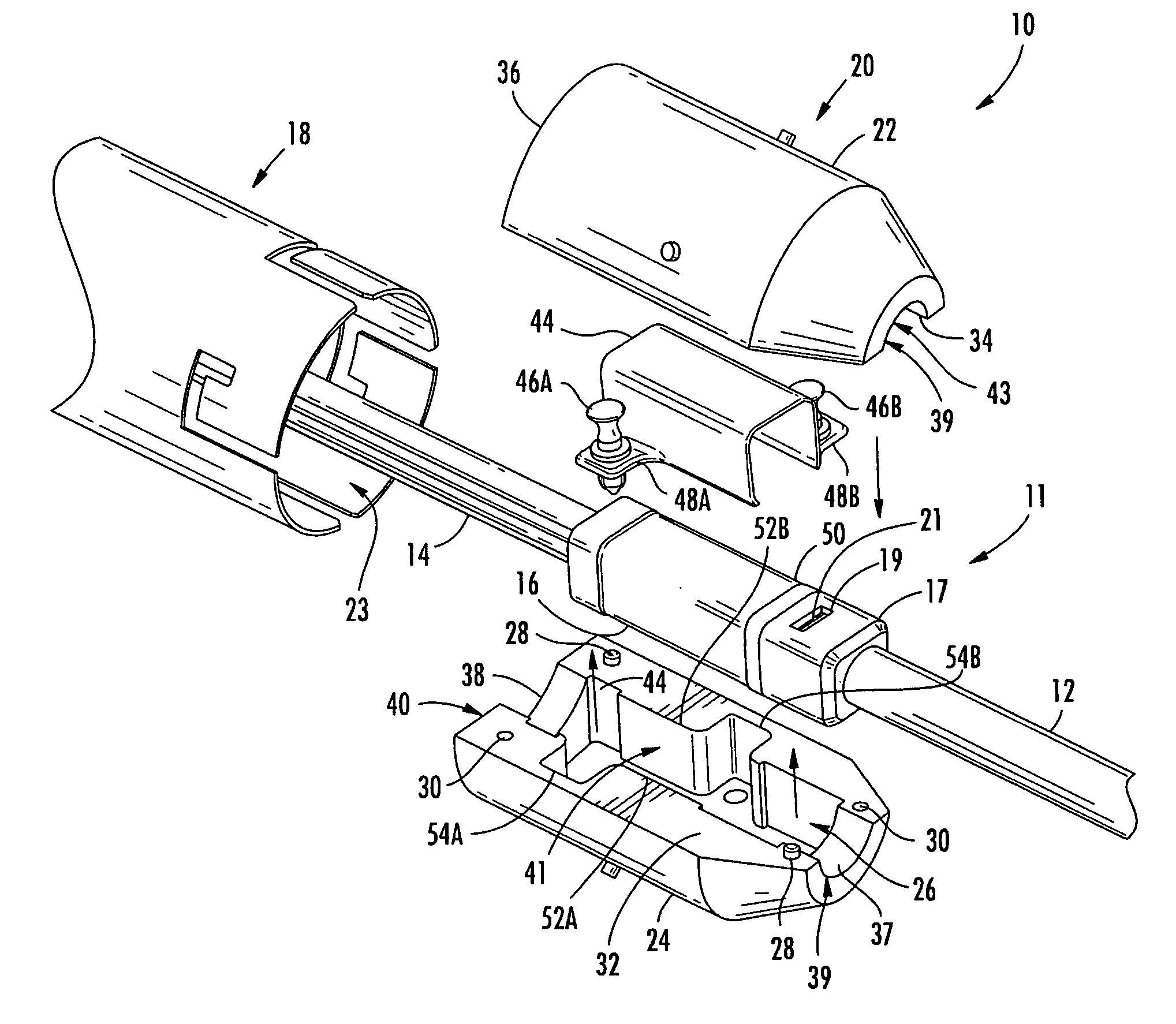
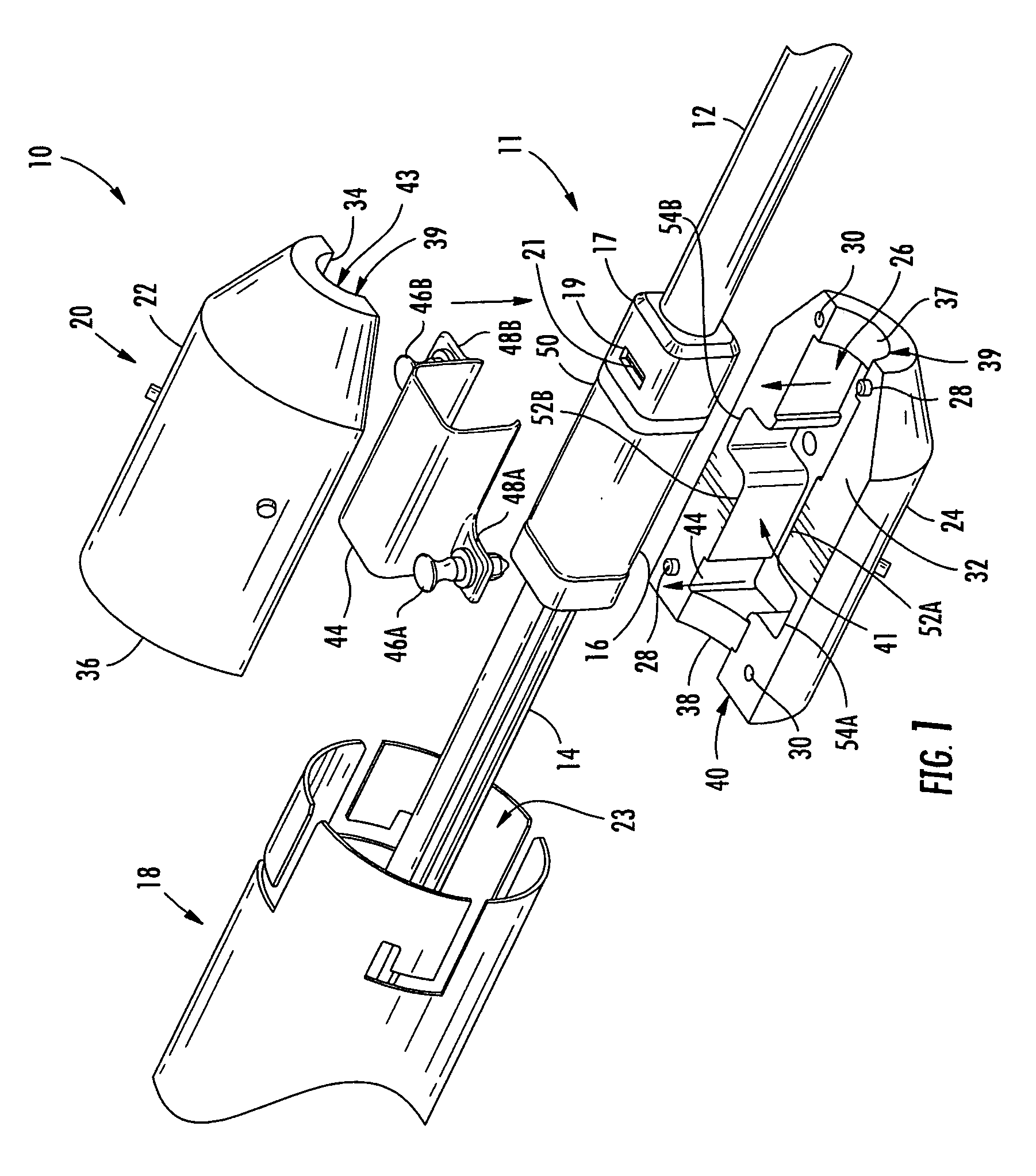
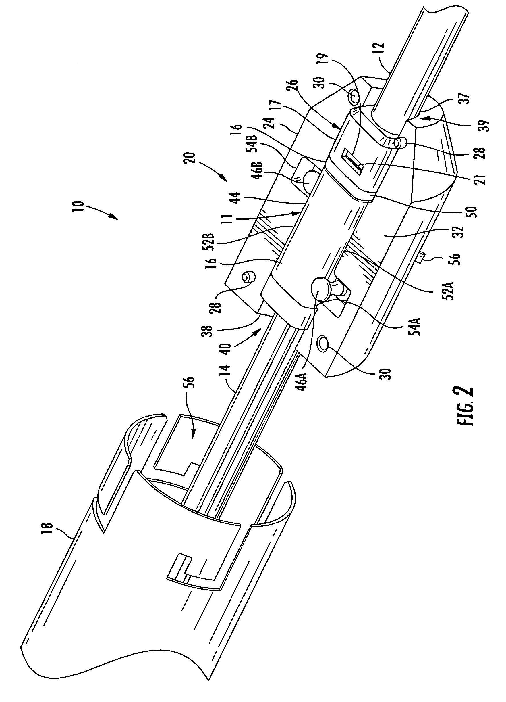
[0011]Embodiments disclosed in the detailed description include pulling grip assemblies for a fiber optic assembly. In one embodiment, the pulling grip assembly is comprised of a pulling grip housing for receiving part of a fiber optic assembly. A pulling grip sleeve is also provided. The pulling grip housing and pulling grip sleeve are secured together using one or more locking features. In this manner, the pulling grip housing can easily be secured to the pulling grip sleeve and removed when pulling of a fiber optic assembly is completed. The pulling grip housing and pulling grip sleeve can also be reused for pulling other fiber optic assemblies.
[0012]Additional features and advantages of the invention will be set forth in the detailed description which follows, and in part will be readily apparent to those skilled in the art from that description or recognized by practicing the invention as described herein, including the detailed description that follows, the claims, as well as ...
PUM
 Abstract
Description
Claims
Application Information