Image converter

a technology of image converter and fisheye lens, which is applied in the field of image converter, can solve the problems of difficult to obtain such a distortion-free planar regular image, unsuitable general photographic use, and circular distortion of images photographed by using fisheye lenses, and achieve the effect of less distortion

Inactive Publication Date: 2010-03-04
DAI NIPPON PRINTING CO LTD
View PDF5 Cites 52 Cited by
  • Summary
  • Abstract
  • Description
  • Claims
  • Application Information

AI Technical Summary

Benefits of technology

[0009]According to the image converter of the present invention, such processing is conducted so that individual pixels of a distorted circular image on a two-dimensional XY orthogonal coordinate system are allowed to correspond to pixels on a two-dimensional UV curved coordinate system which is curved along the side face of a cylindrical column. Therefore, it is possible to obtain a planar regular image by cutting out any desired part from a distorted circular image photographed by use of a fisheye lens and also obtain a planar regular image with less distortion.

Problems solved by technology

However, images photographed by use of a fisheye lens are distorted in circular images, and the images may be used for artistic pictures, as they are, but not suitable for general photographic uses.
However, it is difficult to obtain such a distortion-free planar regular image that can satisfy the above demand by using image converters conventionally proposed.
However, the thus obtained planar regular image is distorted and inadequate for an application to confirm detailed features of a person.
In particular, since the thus obtained rectangular planar regular image is greatly distorted in particular at an external part (in the vicinity of a contour), it is impossible to obtain a smooth panning image in a case where a cut-out portion is gradually moved to conduct a horizontal panning.
However, a panoramic image obtained by this technique is distorted greatly in the perpendicular direction although distorted to a small extent in the horizontal direction, and restriction is imposed on a region at which an image can be cut out.
More specifically, even if a semi-sphere region is photographed, a planar regular image which is cut out from the vicinity of the top is greatly distorted.
Therefore, it is actually impossible to cut out the vicinity of the top.
As described above, if restriction is imposed on a part of an image that can be cut out, it is unfavorable because a blind spot is caused when the technique is applied to a security camera.

Method used


Image

  • Image converter
  • Image converter
  • Image converter

Examples


Embodiment Construction

[0091]Hereinafter, a description will be given for embodiments which illustrate the present invention.

>>

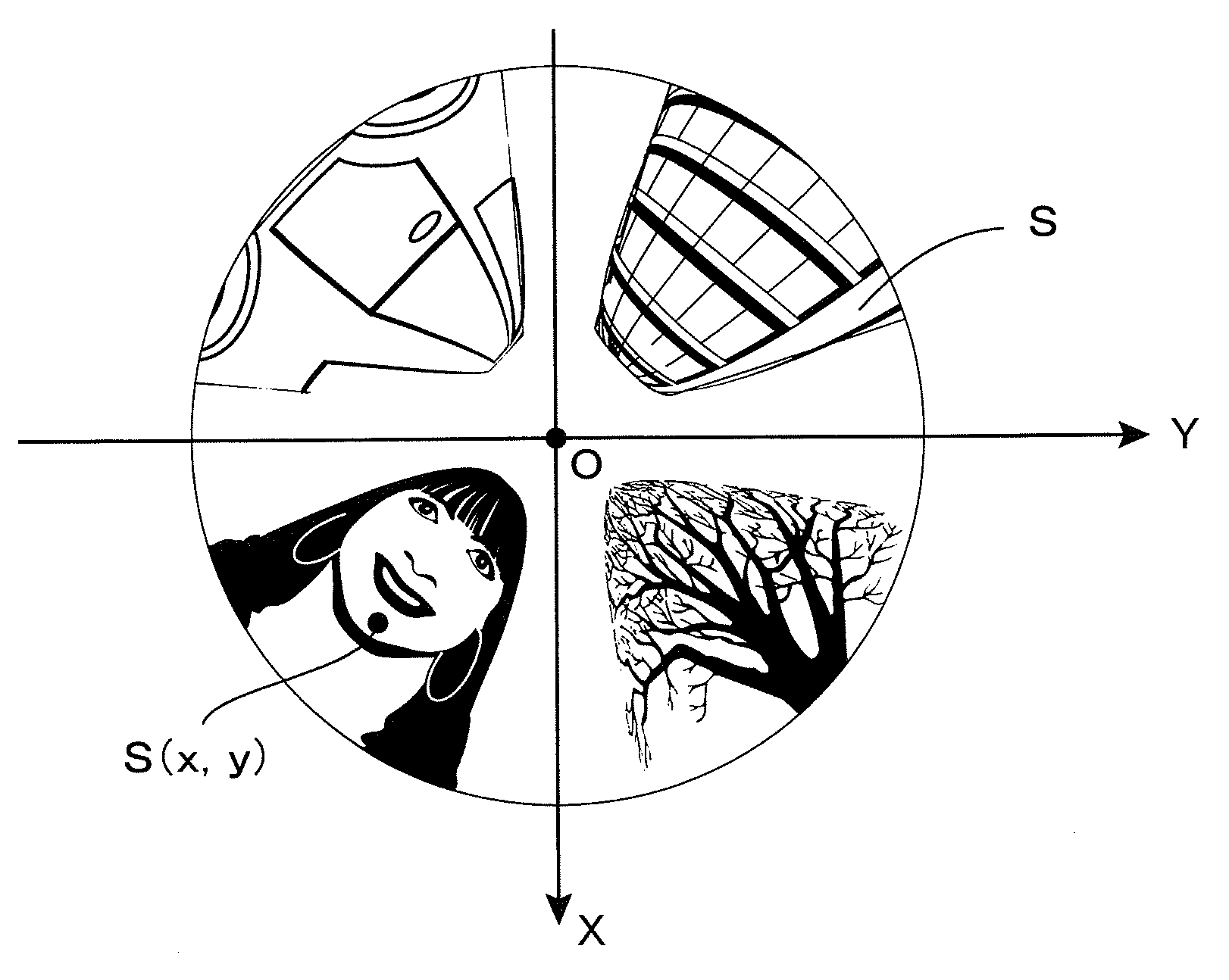
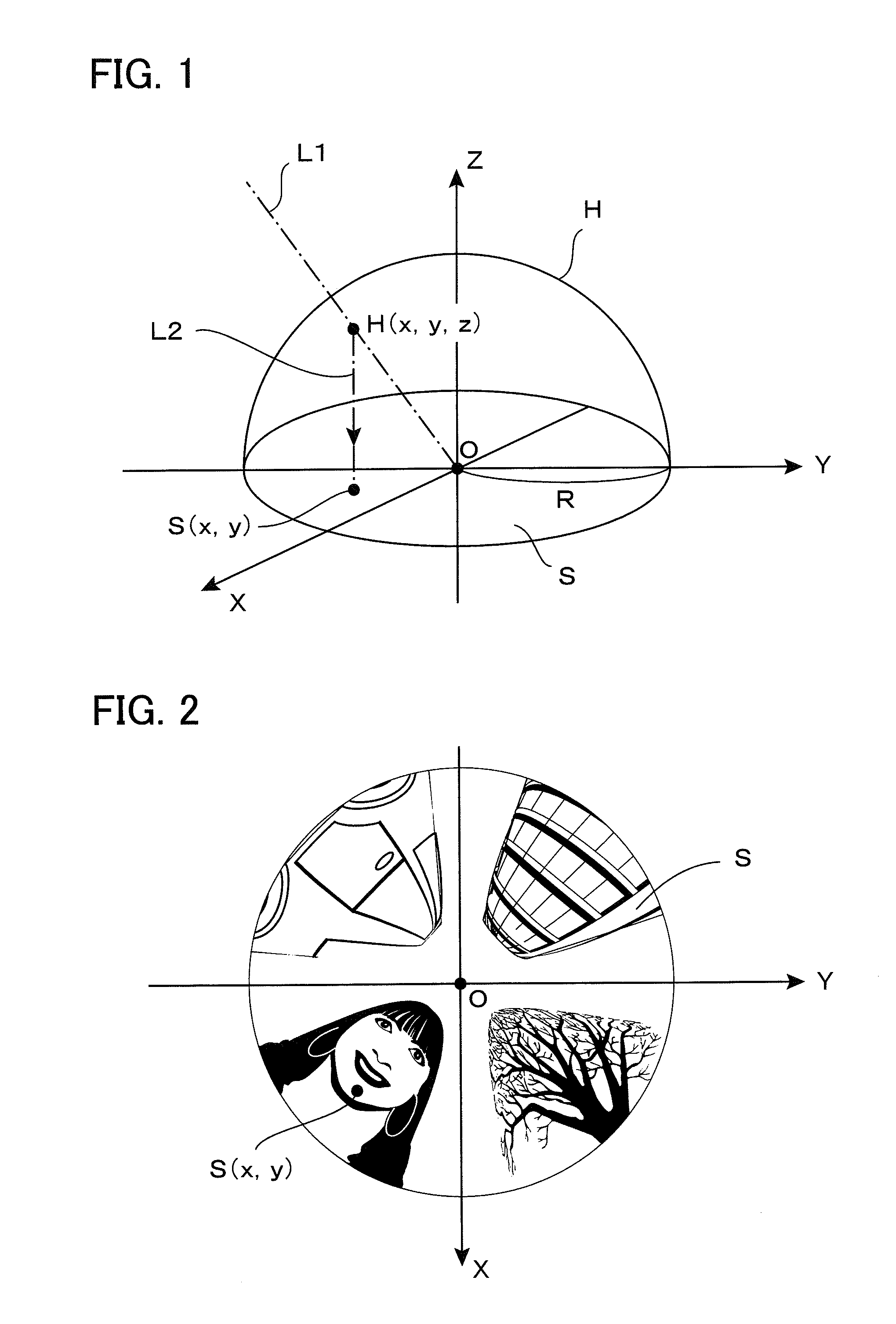
[0092]First, a description will be given for general characteristics of a distorted circular image photographed by use of a fisheye lens and a basic principle of cutting out a part thereof and converting it into a planar regular image. FIG. 1 is a perspective view showing a basic model of forming a distorted circular image S by photographing by use of a fisheye lens based on the orthogonal projection method. In general, fisheye lenses are classified into plural types, depending on projection methods thereof. The model shown in FIG. 1 is a fisheye lens based on the orthogonal projection method (a method for applying the present invention to fisheye lens based on projection other than those based on the orthogonal projection method will be described in Section 5).

[0093]FIG. 1 shows an example in which a distorted circular image S is formed on the XY plane in a three-dimensional XYZ ...


PUM


Abstract

Any given part is cut out from a distorted circular image photographed by use of a fisheye lens and converted into a planar regular image with less distortion. A virtual sphere H having a radius R on a distorted circular image S on an XY plane is defined, thereby allowing a user to designate a cut-out center point P, a magnification m, and a planar inclination angle φ. A visual line vector n passing through an intersecting point Q immediately above the point P is determined to define an UV orthogonal coordinate system having an orientation depending on the angle φ on a plane orthogonal to a visual line vector n at a point G in which a distance between two points OG is given as m·R. The UV orthogonal coordinate system is curved along the side face C of a “virtual cylindrical column in which the point G forms one point on the side face to have a straight line V′ parallel to the V axis and also passing through the point O as a central axis,” thereby defining the UV curved coordinate system. Correspondence relationship equations between a point Ci (ui, vi) on the UV curved coordinate system and a point Si (xi, yi) on the XY coordinate system are used to obtain an image in the vicinity of a point P on the UV curved coordinate system, and the image is expanded on a plane T to obtain a planar regular image.

Description

BACKGROUND OF THE INVENTION [0001]The present invention relates to an image converter and in particular to an apparatus for conducting processes of cutting out a part of a distorted circular image photographed by use of a fisheye lens and converting it into a planar regular image.[0002]A fisheye lens can be used to obtain hemispherical circular images in all directions without using a mechanical moving mechanism. Therefore, a fisheye lens has been extensively used in photographing scenic pictures and others aiming at eccentric effect. However, images photographed by use of a fisheye lens are distorted in circular images, and the images may be used for artistic pictures, as they are, but not suitable for general photographic uses.[0003]Thus, there has been proposed an apparatus for conducting process of converting a distorted circular image photographed by use of a fisheye lens into a planar regular image with less distortion. For example, Japanese Patents No. 3012142 and No. 3051173...

Claims


Application Information

Patent Timeline
Patent Type & Authority Applications(United States)
IPC IPC(8): H04N7/18G06K9/36
CPCG06T3/0062G06T3/0093G06T5/006
Inventor INAGAKI, KOJI
Owner DAI NIPPON PRINTING CO LTD
Why Eureka
Try Eureka