Printing apparatus, printing system, and printing method
a printing system and printing method technology, applied in the field of printing system, printing apparatus, printing method, etc., can solve the problem of poor image of printed matter
- Summary
- Abstract
- Description
- Claims
- Application Information
AI Technical Summary
Benefits of technology
Problems solved by technology
Method used
Image
Examples
first embodiment
[Explanation of System Outline]
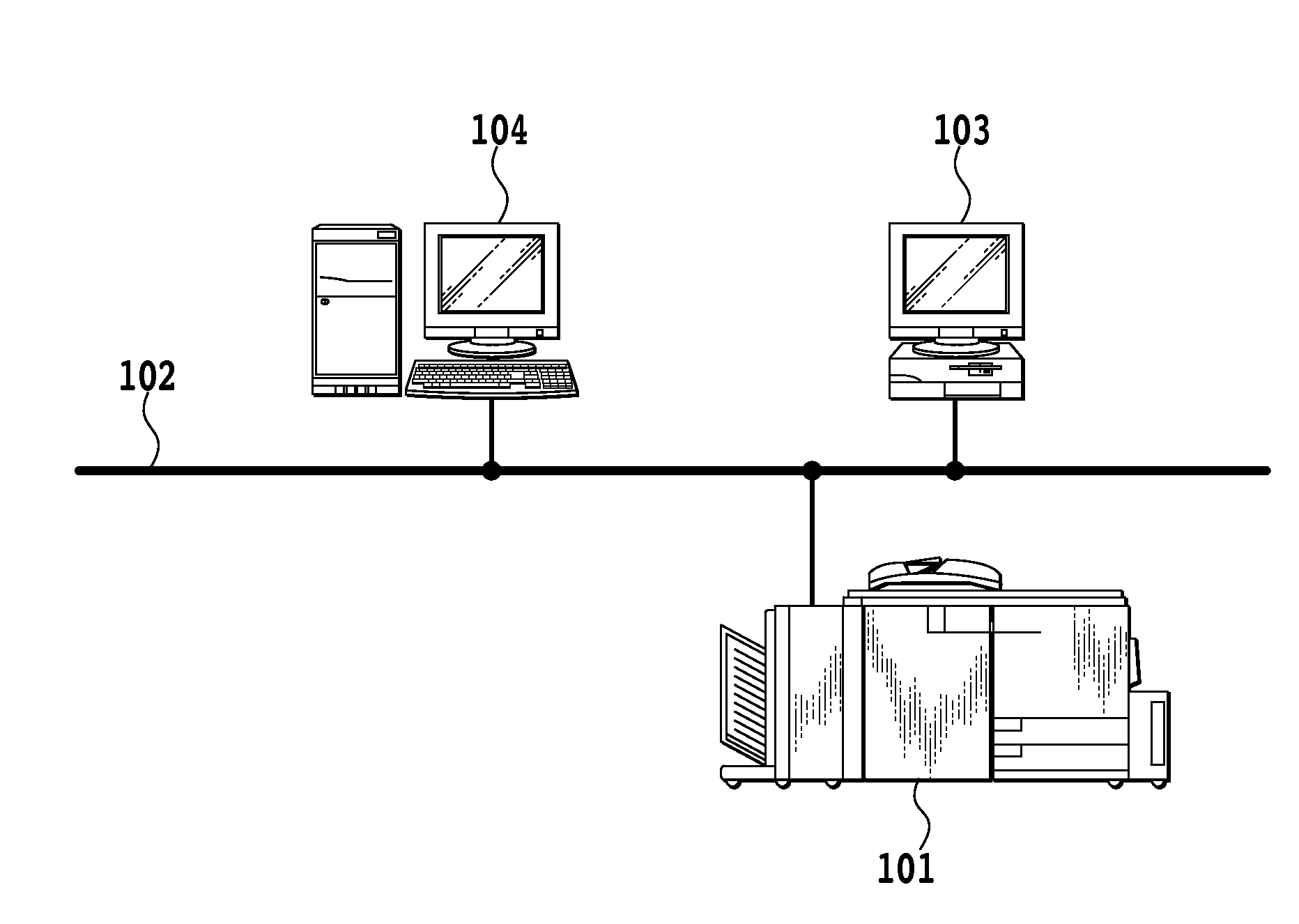
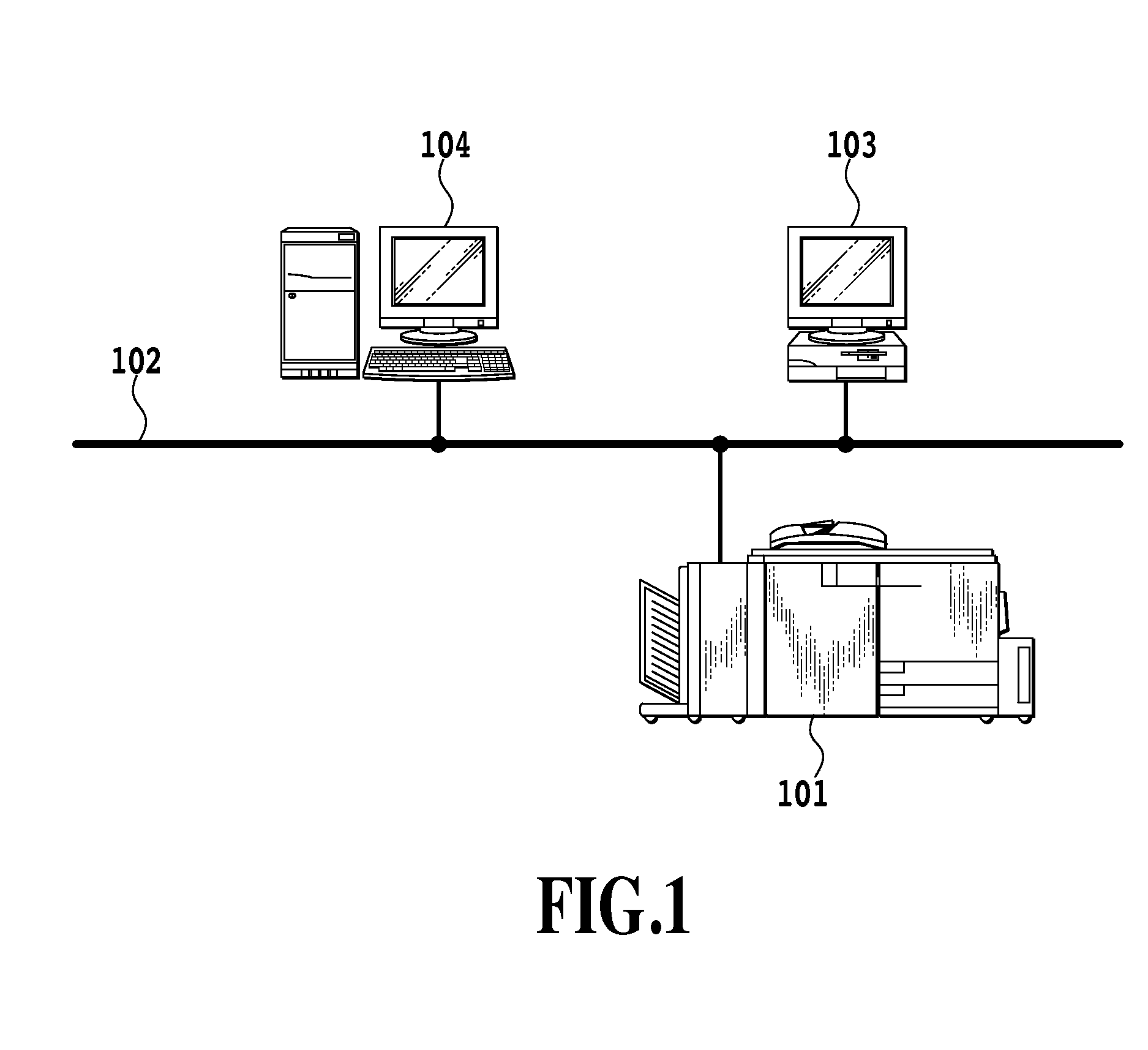
[0018]FIG. 1 is a block diagram showing a configuration of an image processing system according to the present invention. The present image processing system, that is, an image printing system, includes an image forming apparatus (printing apparatus) 101, a print server 104, and a computer terminal 103 connected to a network 102.
[Configuration of an Image Forming Apparatus]
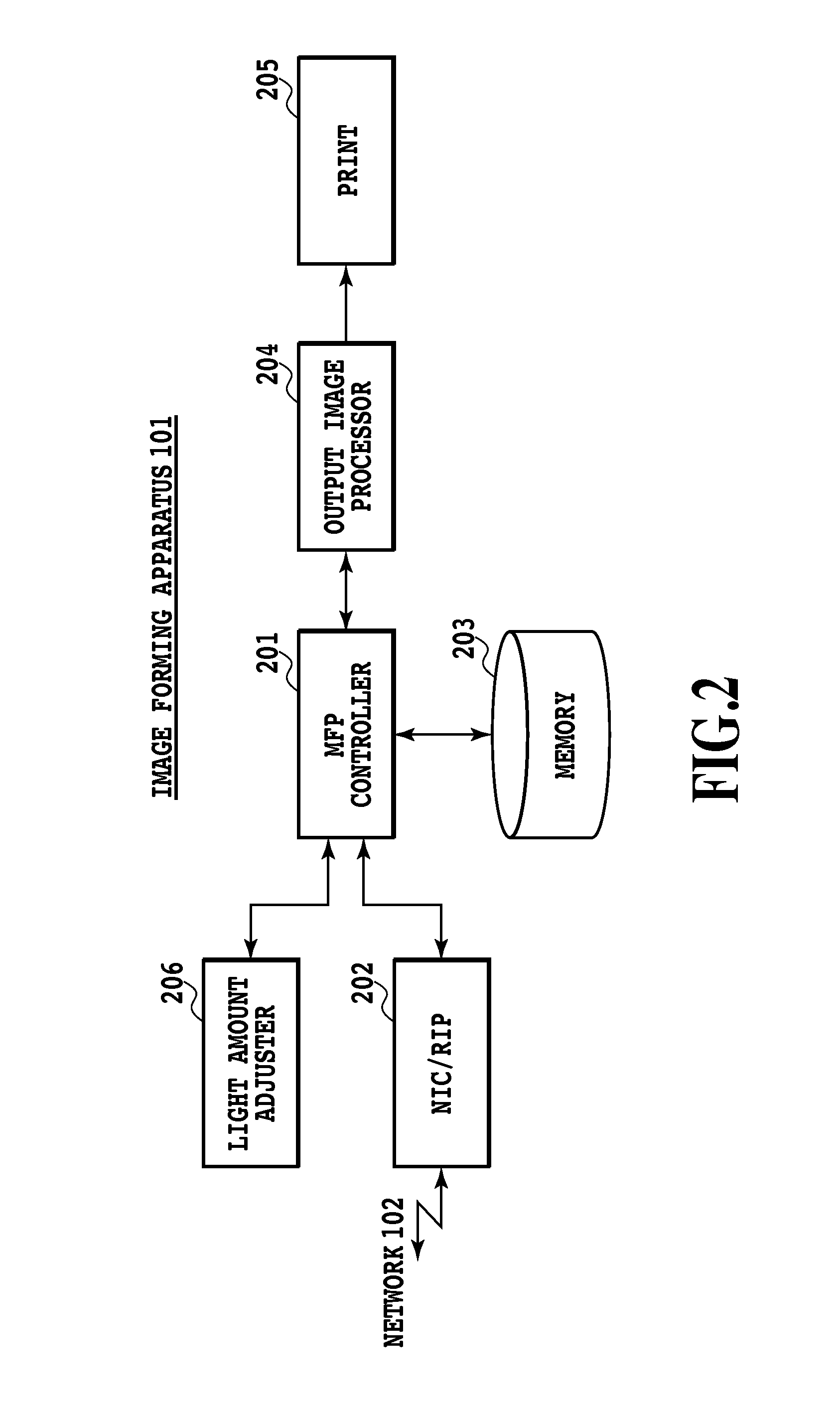
[0019]Using FIG. 2, a configuration of a printing apparatus according to the present invention, that is, an image forming apparatus (MFP: Multi Function Printer) will be described.
[0020]When image data is input to the multi function printer 101 in FIG. 1 from the print server 104 or the computer terminal 103 via the network 102, an NIC unit / RIP unit 202 in FIG. 2 operates as follows. That is, the NIC unit / RIP unit 202 receives the input image data (mainly, PDL data), interprets the received image data, and performs the RIP (Raster Image Processor) development.
[0021]Next, the develope...
second embodiment
[0044]FIG. 6 is a flowchart in a second embodiment, in which the gamma correction is performed using the print server 104. The advantage of using the print server 104 is that output image processing, such as the RIP processing and gamma correction, can be performed at a higher speed than the multi function printer and that the output of printed matter of the multi function printer can be produced quickly. Further, it is also possible for a user to confirm the output image processing result on the display of the print server 104.
[0045]In the form of an output that is not via or bypasses a print server, such as when the multi function printer 101 copies or when the computer terminal 103 directly instructs the multi function printer 101 to print, it is necessary to perform output image processing in the multi function printer 101.
[0046]Because of this, in the present embodiment, the print server 104 is made to have the same capability as that of the output image processor 204 shown in ...
third embodiment
[0059]FIG. 8 is a flowchart in a third embodiment that uses a print server.
[0060]In the present embodiment, as in the second embodiment, the print server 104 is made to have the same capability as that of the output image processor 204 shown in FIG. 3. The block configuration of the print server 104 is the same as that in the second embodiment shown in FIG. 7.
[0061]The MFP controller 201 performs step S801 at various timings when the density characteristics of an output image vary and stops printing to perform calibrations. Each processing in the flowchart is performed each time calibrations are performed.
[0062]In step S802, the MFP controller 201 notifies the light amount adjuster 206 to perform calibrations. The light amount adjuster 206 receives the notification from the MFP controller 201 and performs calibrations, calculates an optimum value of the maximum density, and stores the optimum value along with the index in the memory 203. Further, the light amount adjuster 206 update...
PUM
| Property | Measurement | Unit |
|---|---|---|
| density | aaaaa | aaaaa |
| temperature | aaaaa | aaaaa |
| humidity | aaaaa | aaaaa |
Abstract
Description
Claims
Application Information
 - R&D
- Intellectual Property
- Life Sciences
- Materials
- Tech Scout
- Unparalleled Data Quality
- Higher Quality Content
- 60% Fewer Hallucinations
Browse by: Latest US Patents, China's latest patents, Technical Efficacy Thesaurus, Application Domain, Technology Topic, Popular Technical Reports.
© 2025 PatSnap. All rights reserved.Legal|Privacy policy|Modern Slavery Act Transparency Statement|Sitemap|About US| Contact US: help@patsnap.com


