
Method and apparatus for determining a prediction mode

a technology of prediction mode and method, applied in the direction of color television with bandwidth reduction, signal generator with optical-mechanical scanning, signal system, etc., can solve the problems of many calculations and time-consuming and achieve the reduction of time and calculation requirements for determining prediction mode. , the effect of improving image prediction efficiency

Inactive Publication Date: 2010-03-04
SAMSUNG ELECTRONICS CO LTD
View PDF11 Cites 77 Cited by
  • Summary
  • Abstract
  • Description
  • Claims
  • Application Information

AI Technical Summary

Benefits of technology

[0008]Methods and apparatuses consistent with the present invention provide a method and apparatus for determining a prediction mode, in which a prediction mode for a current block is predicted based on information about a prediction mode for a previously-encoded reference picture so that image prediction efficiency is improved and also the time required for prediction mode determination and the number of calculations performed for prediction mode determination are reduced.
[0013]In a prediction mode determining method and apparatus consistent with the present invention, image prediction efficiency is improved, and the number of prediction modes actually applied is reduced, so that the time and number of calculations required for prediction mode determination can be reduced.

Problems solved by technology

Thus, this prediction mode determination requires much time and many calculations.

Method used


Image

  • Method and apparatus for determining a prediction mode
  • Method and apparatus for determining a prediction mode
  • Method and apparatus for determining a prediction mode

Examples


Embodiment Construction

[0024]The present invention will now be described more fully with reference to the accompanying drawings, in which exemplary embodiments of the invention are shown.

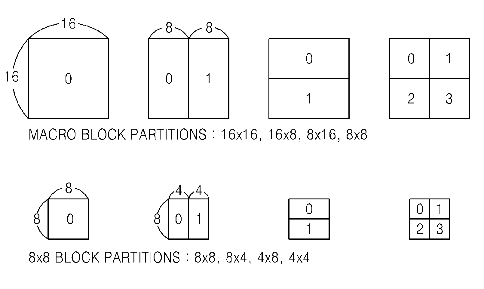
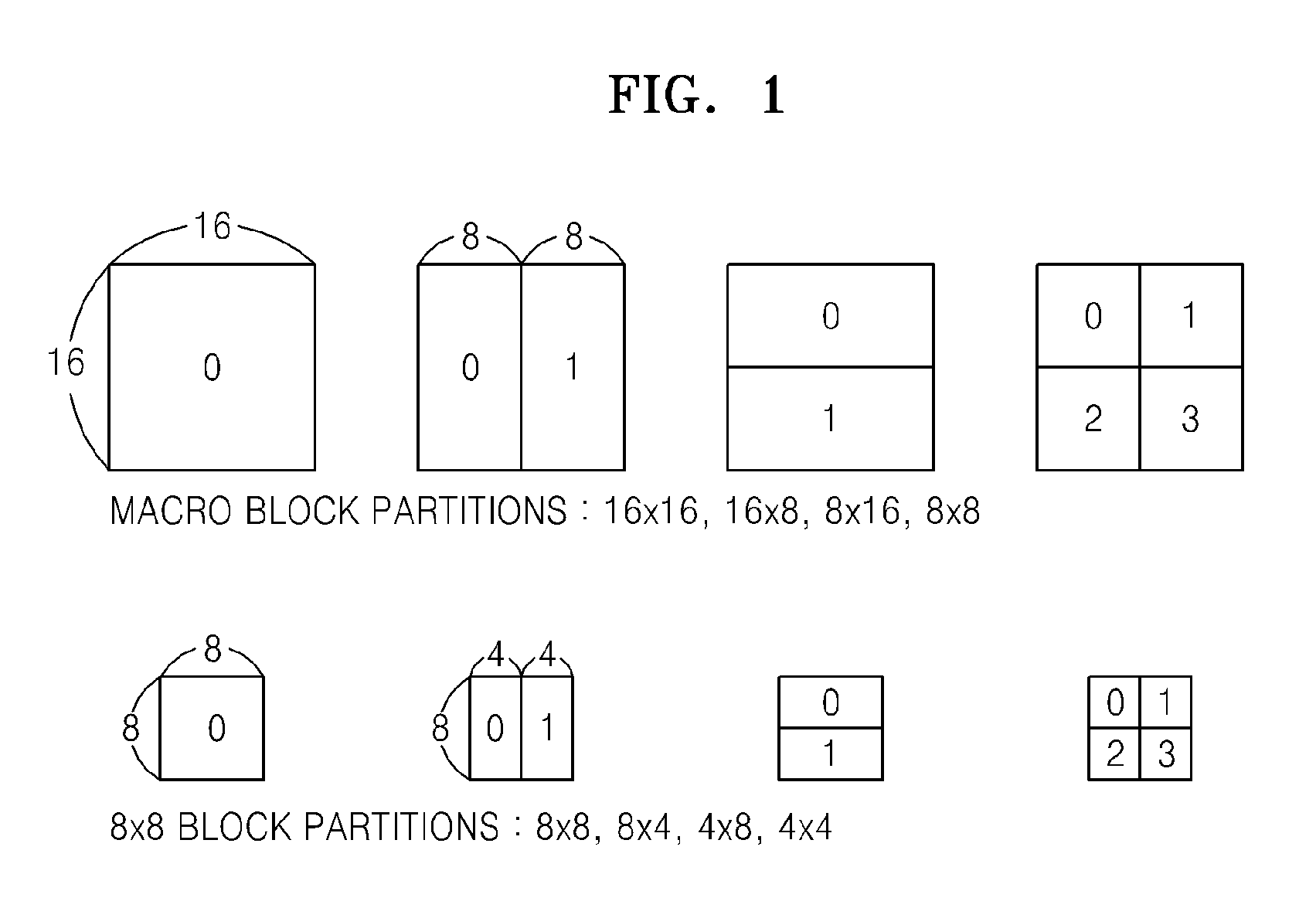
[0025]FIG. 1 is a reference diagram for illustrating a block prediction mode according to an exemplary embodiment of the present invention.

[0026]As shown in FIG. 1, a macroblock may be divided into subblocks of various sizes, such as, 16×16, 16×8, 8×16, 8×8, 8×4, 4×8, and 4×4, and the subblocks may be encoded. Each macroblock is encoded using various prediction modes that can be used in interprediction and intraprediction, and a prediction mode that generates a minimum cost, for example, a minimum rate-distortion (RD) cost, from among the various prediction modes used to encode each macroblock is determined as a final prediction mode for the macroblock. More specifically, during intraprediction, a macroblock is predictively coded in each of an intra 16×16 mode, an intra 8×8 mode, an intra 4×4 mode, etc. During interpredic...


PUM


Abstract

A method and apparatus for determining a prediction mode which is used during encoding of a current block is provided. In the method and apparatus, a prediction mode candidate group to be used for the current block is determined based on a prediction mode for a block positioned at the same location on a reference picture as a location of the current block encoded, predictive coding is performed on the current block by using predictive modes included in the prediction mode candidate group. Thus, image prediction efficient is improved, and the time and number of calculations required for prediction mode determination are reduced.

Description

CROSS-REFERENCE TO RELATED PATENT APPLICATION[0001]This application claims priority from Korean Patent Application No. 10-2008-0086284, filed on Sep. 2, 2008, in the Korean Intellectual Property Office, the disclosure of which is incorporated herein in its entirety by reference.BACKGROUND OF THE INVENTION[0002]1. Field of the Invention[0003]Methods and apparatuses consistent with the present invention relate to determination of a prediction mode, and more particularly, to determining a prediction mode to be actually used among a plurality of available prediction modes.[0004]2. Description of the Related Art[0005]In image compression methods such as MPEG-1, MPEG-2, MPEG-4, H.264 / MPEG-4 AVC (Advanced Video Coding), etc., a single picture is divided into macroblocks in order to encode an image. The macroblocks may be encoded using prediction modes that are available for use in interprediction and intraprediction. A prediction mode is selected based on a bit rate required to encode a ma...

Claims


Application Information

Patent Timeline
IPC IPC(8): H04N7/12
CPCH04N19/176H04N19/61H04N19/573H04N19/132H04N19/157H04N19/103
Inventor YOO, KI-WONAHN, TAE-GYOUNGLEE, JAE-HUN
Owner SAMSUNG ELECTRONICS CO LTD
Learn More