X-ray imaging apparatus

Inactive Publication Date: 2010-03-04
CANON KK
View PDF5 Cites 18 Cited by
  • Summary
  • Abstract
  • Description
  • Claims
  • Application Information

AI Technical Summary

Benefits of technology

[0012]The present invention provides an X-ray imaging apparatus that improves portability by size

Problems solved by technology

Thus, a digital examination car in which a thin, lightweight, and portable FPD (Flat Panel Detector) is mounted can immediately perform image recognition and perform an image taking operation again, and development and cassette replacement during another image taking operation and multidirectional image

Method used


Image

  • X-ray imaging apparatus
  • X-ray imaging apparatus
  • X-ray imaging apparatus

Examples


first embodiment

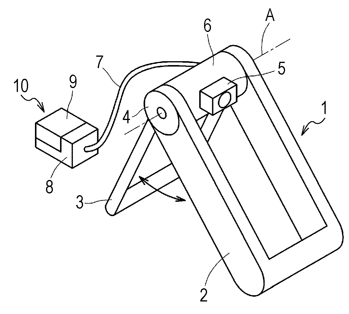
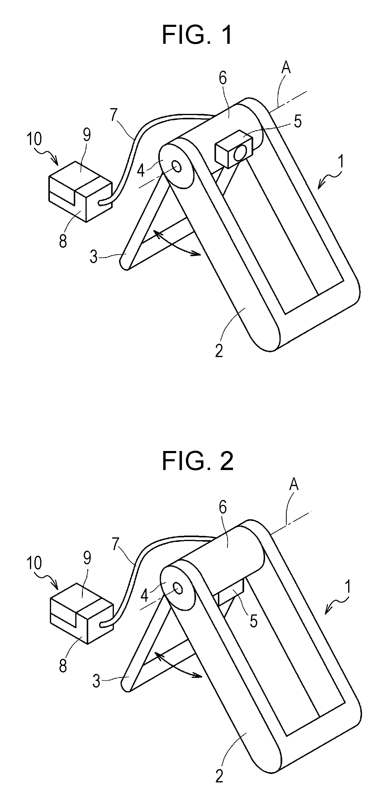
[0035]FIG. 1 is a perspective view of an X-ray imaging apparatus according to a first embodiment. In the X-ray imaging apparatus, a holding unit 1 includes two support legs 2 and 3. In each of the support legs 2 and 3, two supports are connected at a lower side to form a U-shape. Upper ends of the support legs 2 and 3 are turnably connected via a connecting portion 4, whereby the support legs 2 and 3 can be spread. The spread angle between the support legs 2 and 3 can be arbitrarily set by the frictional force of the connecting portion 4. A holding member 6 turnable on an axis A is provided at the top of the holding unit 1. The holding member 6 holds an X-ray tube 5 so that the X-ray tube 5 can emit X-rays at an arbitrary angle.

[0036]The X-ray tube 5 is connected to an X-ray generation control unit 10 via a cable 7. The X-ray generation control unit 10 includes a controller 8 for controlling X-ray radiation by the X-ray tube 5, and a power supply 9 for supplying power for X-ray radi...

second embodiment

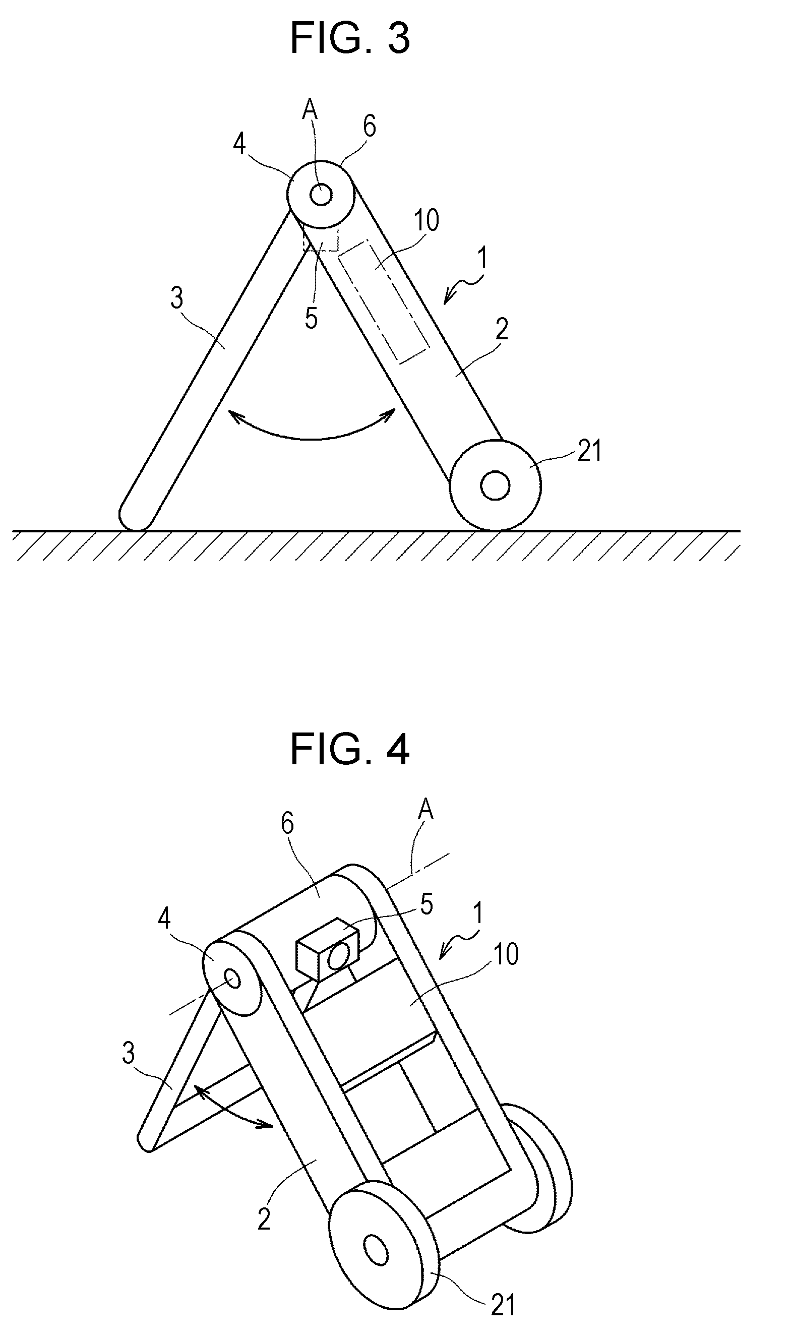
[0039]FIGS. 3 and 4 are a side view and a perspective view, respectively, of an X-ray imaging apparatus according to a second embodiment. The same components as those adopted in the first embodiment are denoted by the same reference numerals. While the X-ray generation unit 10 is provided apart from the holding unit 1 with the cable 7 disposed therebetween in the first embodiment, an X-ray generation control unit 10 in the second embodiment is provided between supports of a support leg 2. Further, a pair of moving wheels 21 are provided at a lower end of at least the support leg 2. These moving wheels 21 improve portability.

[0040]By virtue of the above-described structure, the X-ray imaging apparatus can be easily moved together with the X-ray generation control unit 10 while the support legs 2 and 3 are closed and the weight is received by the moving wheels 21. Thus, portability is improved.

third embodiment

[0041]FIGS. 5 and 6 are a side view and a perspective view, respectively, of an X-ray imaging apparatus according to a third embodiment. In the third embodiment, the X-ray imaging apparatus includes a position changing member that moves an X-ray tube 5 of a holding member 6 up and down.

[0042]A height adjusting shaft 31 serves as the position changing member, and vertically extends through the holding member 6. At an upper end of the height adjusting shaft 31, a second holding member 32 is provided to hold the X-ray tube 5. The height adjusting shaft 31 can change the height of the X-ray tube 5 relative to the holding member 6 by the frictional force, and can rotate about its axis. Further, the second holding member 32 is provided with a grip portion 33 used for carriage.

[0043]Thus, the height of the X-ray tube 5 can be finely adjusted by the height adjusting shaft 31 after being roughly adjusted by the spread angle between the support legs 2 and 3. Moreover, the user can move the X-...


PUM


Abstract

An X-ray imaging apparatus includes an X-ray tube, an X-ray generation control unit configured to control the X-ray tube with a controller and a power supply, and a holding unit configured to hold the X-ray tube. The holding unit includes two support legs to be spread at an arbitrary angle, and a connecting portion configured to turnably connect upper ends of the support legs. The holding unit holds the X-ray tube near the connecting portion.

Description

BACKGROUND OF THE INVENTION[0001]1. Field of the Invention[0002]The present invention relates to an X-ray imaging apparatus that obtains an X-ray image from X-rays transmitted through a subject, and more particularly, to a movable X-ray imaging apparatus for use in image taking performed, for example, at home or at the time of disaster.[0003]2. Description of the Related Art[0004]There are known movable X-ray imaging apparatuses that are moved to the bedside in a patient's room to take an X-ray image of a subject in a state in which an X-ray device is mounted on a carriage. In these X-ray imaging apparatuses, a storage box storing an X-ray film cassette and the like is often provided integrally with an X-ray control unit.[0005]Japanese Patent Laid-Open No. 2000-51189 proposes a movable imaging system in which an X-ray control unit and a storage unit storing an X-ray film cassette are connected detachably.[0006]Japanese Patent Laid-Open No. 2004-208716 proposes a digital X-ray imagin...

Claims


Application Information

Patent Timeline
IPC IPC(8): H05G1/02
CPCA61B6/4405
Inventor OHMURA, SATORUKOBAYASHI, MASAAKIKATO, KATSUSHIICHIYOSHI, HIROYUKI
Owner CANON KK
Why Eureka
Try Eureka