
Optical fiber assemblies for fiber to the subscriber applications

a technology of optical fiber and subscriber, applied in the field of components and optical fiber assemblies, can solve problems such as problems in installing optical fiber networks, and achieve the effect of quick, convenient and reliable installation

Inactive Publication Date: 2010-03-04
CORNING CABLE SYST LLC
View PDF7 Cites 130 Cited by
  • Summary
  • Abstract
  • Description
  • Claims
  • Application Information

AI Technical Summary

Benefits of technology

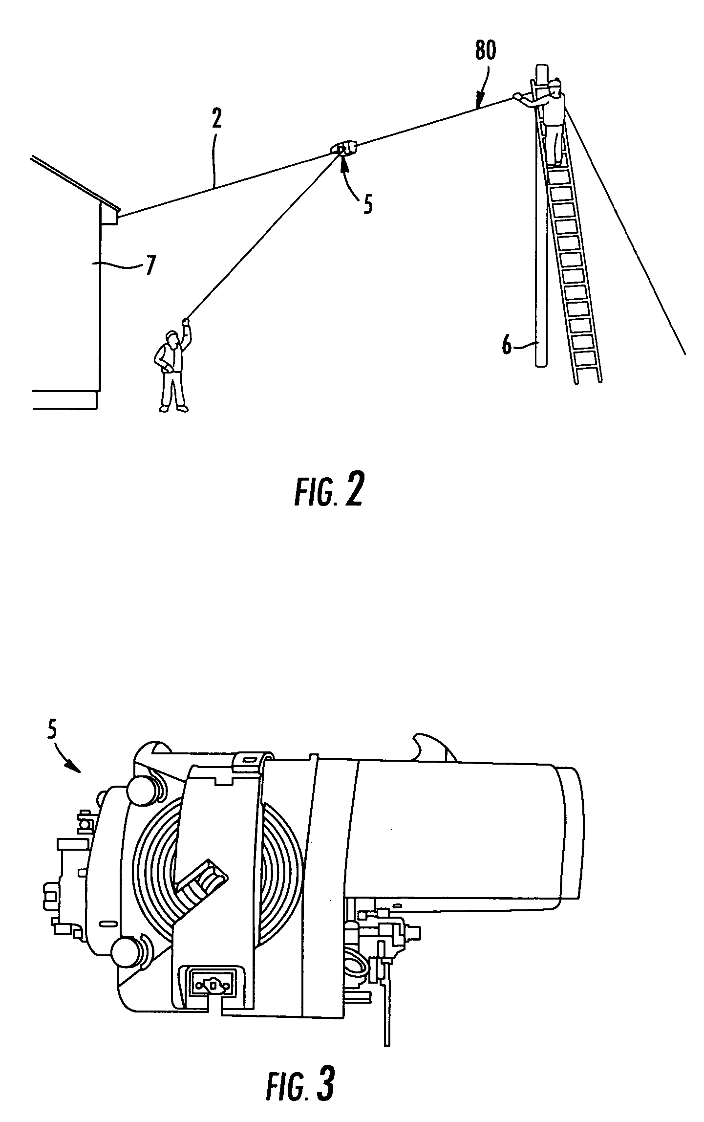
[0006]The disclosure is directed to components, fiber optic assemblies, and / or methods that allow quick, easy, and reliable installation for optical networks. One aspect is directed to a spool for deploying a fiber optic cable in the field using a lashing machine or similar tool. The spool includes a first spool flange and a second spool flange. The first spool flange includes a notch and the second spool flange includes a notch, wherein the notch of the first flange overlaps with the notch of the second flange over a predetermined angular location. In further embodiments, the spool can have at least one optical fiber connector and / or splitter attached thereto. Consequently, the spool may make an optical connection when attached to an enclosure or other suitable device having a complementary mating feature.

Problems solved by technology

However, there are challenges for installing optical fiber networks.

Method used


Image

  • Optical fiber assemblies for fiber to the subscriber applications
  • Optical fiber assemblies for fiber to the subscriber applications
  • Optical fiber assemblies for fiber to the subscriber applications

Examples


Embodiment Construction

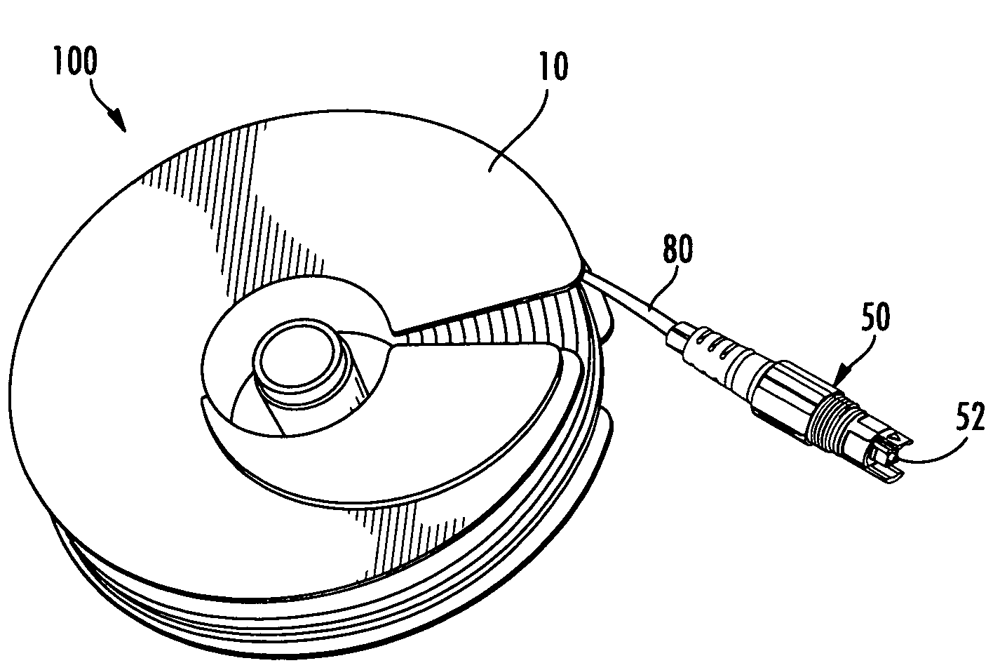
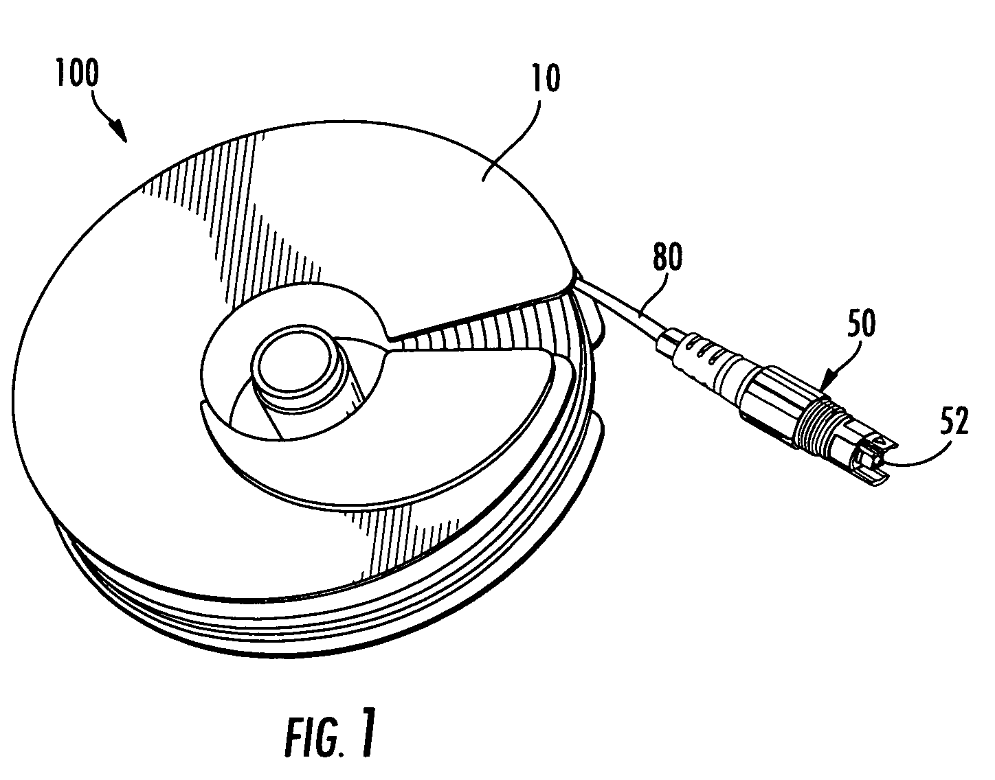
[0025]Reference will now be made in detail to the present preferred embodiments of the invention, examples of which are illustrated in the accompanying drawings. Whenever possible, the same reference numerals will be used throughout the drawings to refer to the same or like parts. FIG. 1 is a perspective view of an explanatory fiber optic assembly 100 according to the present invention. Fiber optic assembly 100 includes a spool 10 and a fiber optic cable 80, where at least a portion of fiber optic cable 80 is disposed on spool 10. Fiber optic cable 80 has a relatively small cross-section and is highly flexible so that it can be wrapped onto spool 10, while still being robust to preserve optical performance. Fiber optic assembly 100 may optionally include at least one fiber optic connector 52 attached to a first end of fiber optic cable 80. As best shown in FIG. 9, fiber optic assembly 100 employs fiber optic connector 52 as a portion of a hardened fiber optic plug 50, thereby provid...


PUM


Abstract

Disclosed are spools, fiber optic assemblies, and methods for use with a lashing machine or other suitable deployment for routing the fiber optic cable toward the subscriber allowing the craft to quickly and easily deploy the fiber optic cable in the field. The fiber optic assemblies may include a spool, at least one fiber optic cable disposed on the spool, and a fiber optic connector. In one embodiment, the spool includes a first spool flange and a second spool flange that include notches that overlap at angular positions for allowing the spooling of fiber optic cable off the same. In another embodiment, the fiber optic connector is attached to the spool for plug and play connectivity of the spool. In other embodiments, a splitter may be attached to the spool for splitting the optical signal.

Description

BACKGROUND OF THE INVENTION [0001]1. Field of the Invention[0002]Disclosed are components, optical fiber assemblies, and methods useful for fiber to the subscriber and other applications. More particularly, the disclosure relates to spools and optical fiber assemblies having fiber optic cables disposed on relatively small spools that may interface with other components for deployment.[0003]2. Technical Background[0004]Communications networks are used to transport a variety of signals such as voice, video, data and the like. As communications applications required greater bandwidth, communication networks switched to cables having optical fibers since they are capable of transmitting an extremely large amount of bandwidth compared with a copper conductor. Moreover, a fiber optic cable is much smaller and lighter compared with a copper cable having the same bandwidth capacity. As optical waveguides are deployed deeper into communication networks, subscribers will have access to increa...

Claims


Application Information

Patent Timeline
IPC IPC(8): G02B6/00
CPCB65H75/14G02B6/4457B65H2701/534B65H75/182
Inventor LOCHKOVIC, GREGORY A.OTT, MICHAEL J.SERRANO, JORGE R.KNECHT, DENNIS M.
Owner CORNING CABLE SYST LLC
Learn More