Multi-port accumulator for radio-over-fiber (RoF) wireless picocellular systems

a wireless picocellular and multi-port technology, applied in electromagnetic transmission, electrical equipment, transmission, etc., can solve the problems of reducing the service life of the wireless system/network, and affecting the reliability of the wireless system

Inactive Publication Date: 2010-03-04
CORNING CABLE SYST LLC
View PDF99 Cites 65 Cited by
  • Summary
  • Abstract
  • Description
  • Claims
  • Application Information

AI Technical Summary

Benefits of technology

[0010]One aspect of the invention is a multi-port accumulator apparatus for operably supporting two or more RoF transponders and for providing a connection to a tail cable that carries uplink and downlink optical signals and electrical power. The apparatus includes a housing and two or more RoF transponder ports supported by the housing, with each RoF transponder port configured to operably connect to one of the RoF transponders. The apparatus also includes a tail cable port supported by the housing and configured to operably connect to the tail cable. The tail cable port is optically and electrically connected to each RoF transponder port so as to provide the uplink and downlink optical signals and the electrical power to each RoF transponder.

Problems solved by technology

This makes the wireless system / network relatively complex and difficult to scale, particularly when many picocells need to cover a large region.
Further, the digital information processing performed at the access point devices requires that these devices be activated and controlled by the head-end controller, which further complicates the distribution and use of numerous access point devices to produce a large picocellular coverage area.
One shortcoming relates to the relative difficulty in manufacturing and deploying an optical fiber cable having a linear array of transponders.
Each transponder needs to be optically coupled to an uplink optical fiber and a downlink optical fiber as well as to an electrical power line, usually via a “tether cable.” This involves the tedious and time-consuming process of accessing the uplink and downlink optical fibers and the electrical power line in the cable, splicing the optical fibers and electrical power line, and then connecting them to the transponder.
Another shortcoming of the linear array approach for distributing transponders is that the approach is not readily scalable once the system is deployed.
This makes it difficult to quickly and inexpensively change the picocell coverage area to accommodate the changing needs or geometry of the particular wireless environment.

Method used


Image

  • Multi-port accumulator for radio-over-fiber (RoF) wireless picocellular systems
  • Multi-port accumulator for radio-over-fiber (RoF) wireless picocellular systems
  • Multi-port accumulator for radio-over-fiber (RoF) wireless picocellular systems

Examples


Embodiment Construction

[0030]Reference is now made in detail to certain embodiments of the invention, examples of which are illustrated in the accompanying drawings. Whenever possible, the same or analogous reference numbers are used throughout the drawings to refer to the same or like parts.

Generalized Optical-Fiber-Based RoF Wireless Picocellular System

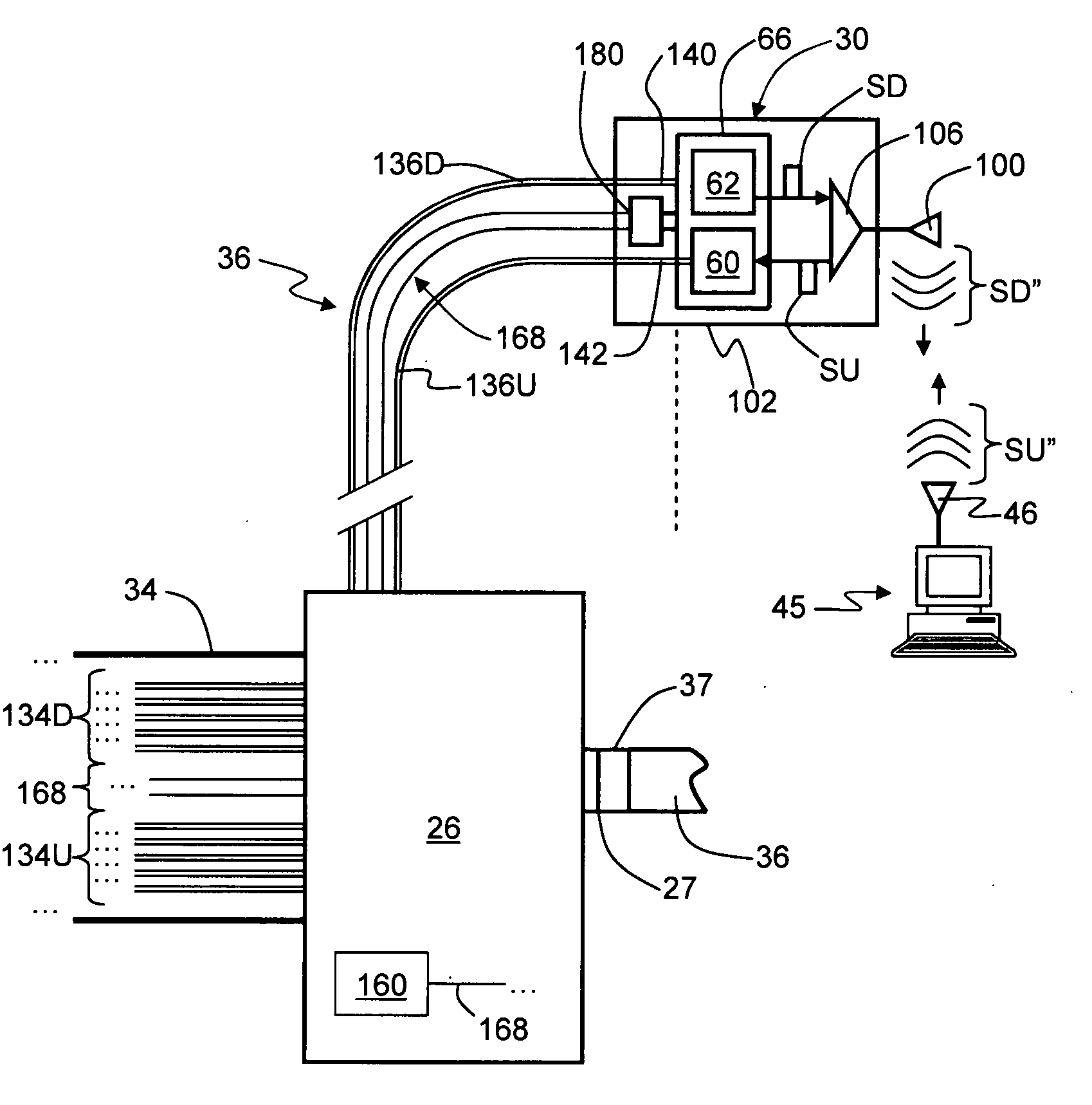
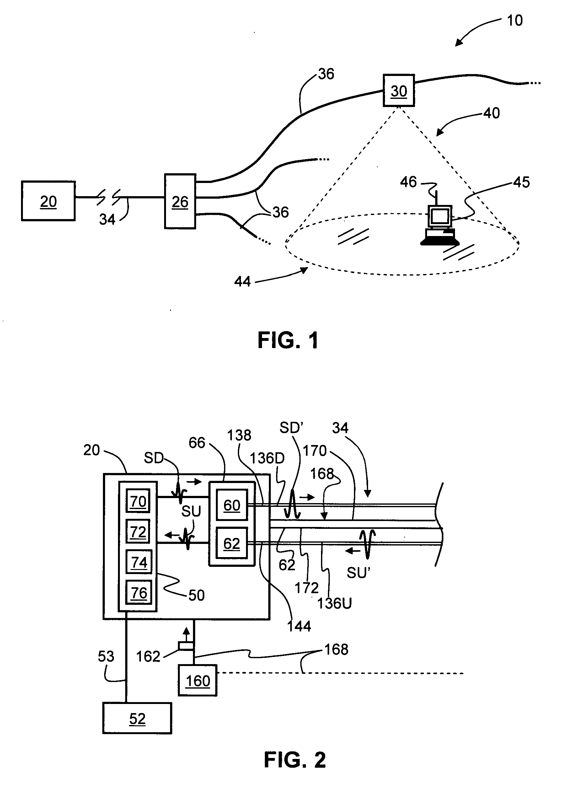
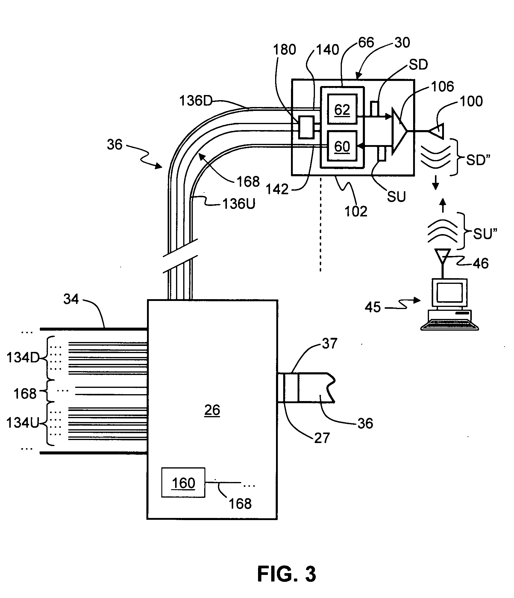
[0031]FIG. 1 is a schematic diagram of a generalized example embodiment of an optical-fiber-based RoF wireless picocellular system 10. System 10 includes a head-end unit 20, a distribution unit 26, at least one RoF transponder unit (“transponder”) 30, a primary optical fiber RF communication link 34 that optically couples the head-end unit to the distribution unit, and at least one secondary optical fiber RF communication link 36 that couples one or more transponders to the distribution unit, thus establishing a connection between the transponder(s) and the head-end unit. In an example embodiment, optical fiber RF communication links 34 and 36 include at ...


PUM


Abstract

A multi-port accumulator apparatus for a radio-over-fiber (RoF) wireless picocellular system that includes a housing that supports a tail cable port and a number of RoF transponder ports. The tail cable port is optically coupled to the RoF transponder ports so as to provide for optical transmission of uplink and downlink optical signals between the tail cable port and each of the transponder ports. The tail cable port is also electrically coupled to each transponder port so as to provide electrical power to each of the plurality of transponder ports. The multi-port accumulator supports two or more RoF transponders, one at each RoF transponder port. Each RoF transponder includes a directional antenna system that forms a picocellular coverage sub-area, with the combined sub-areas constituting a picocellular coverage area for the multi-port accumulator. The multi-port accumulator allows for the quick installation and deployment of large numbers of RoF transponders without having to individually connect each RoF transponder to a pair of downlink and uplink optical fibers carried by an optical fiber RF communication link.

Description

BACKGROUND OF THE INVENTION[0001]1. Field of the Invention[0002]The present invention relates generally to wireless communication systems, and in particular relates to transponders and transponder systems and methods used in optical-fiber-based wireless picocellular systems for radio-over-fiber (RoF) communication.[0003]2. Technical Background[0004]Wireless communication is rapidly growing, with ever-increasing demands for high-speed mobile data communication. As an example, so-called “wireless fidelity” or “WiFi” systems and wireless local area networks (WLANs) are being deployed in many different types of areas (coffee shops, airports, libraries, etc.). Wireless communication systems communicate with wireless devices called “clients,” which must reside within the wireless range or “cell coverage area” in order to communicate with the access point device.[0005]One approach to deploying a wireless communication system involves the use of “picocells,” which are radio-frequency (RF) c...

Claims


Application Information

Patent Timeline
Patent Type & Authority Applications(United States)
IPC IPC(8): H04B10/00
CPCH04B10/25754H04W88/085H04B10/808
Inventor LOGAN, ERIC RAYMOND
Owner CORNING CABLE SYST LLC
Why Eureka
Try Eureka