Circumferential Shroud Inserts for a Gas Turbine Vane Platform

a technology of turbine vanes and shrouds, which is applied in the direction of machines/engines, stators, liquid fuel engines, etc., can solve the problems of high operating temperature and thermal stress on the surface of the vane assemblies exposed to working gas, rotation of the shaft, and cracks on the vane platforms

Active Publication Date: 2010-03-04
SIEMENS ENERGY INC
View PDF20 Cites 46 Cited by
  • Summary
  • Abstract
  • Description
  • Claims
  • Application Information

AI Technical Summary

Problems solved by technology

Expansion of the working gas through the turbine assembly results in a transfer of energy from the working gas to the rotating blades, causing rotation of the shaft.
However, the surfaces of the vane assemblies exposed to the working gas are subjected to high operational temperatures and t

Method used


Image

  • Circumferential Shroud Inserts for a Gas Turbine Vane Platform
  • Circumferential Shroud Inserts for a Gas Turbine Vane Platform
  • Circumferential Shroud Inserts for a Gas Turbine Vane Platform

Examples


Embodiment Construction

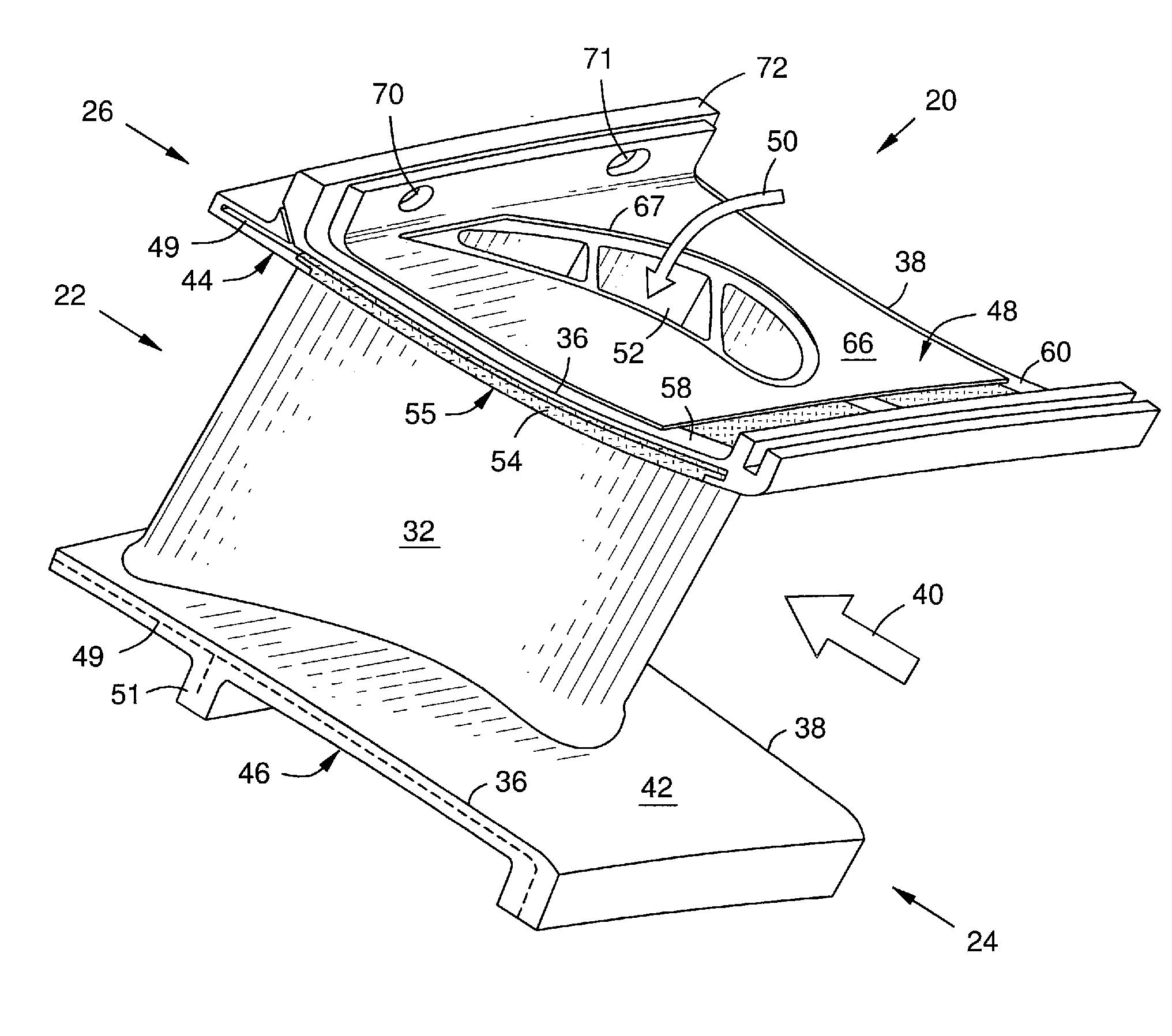
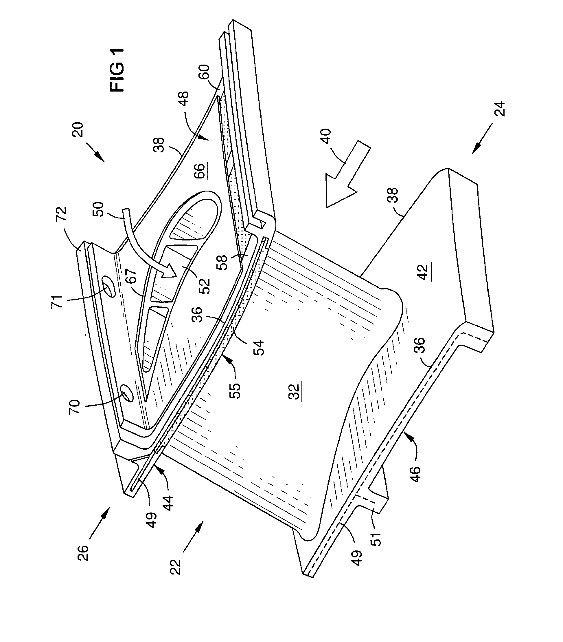
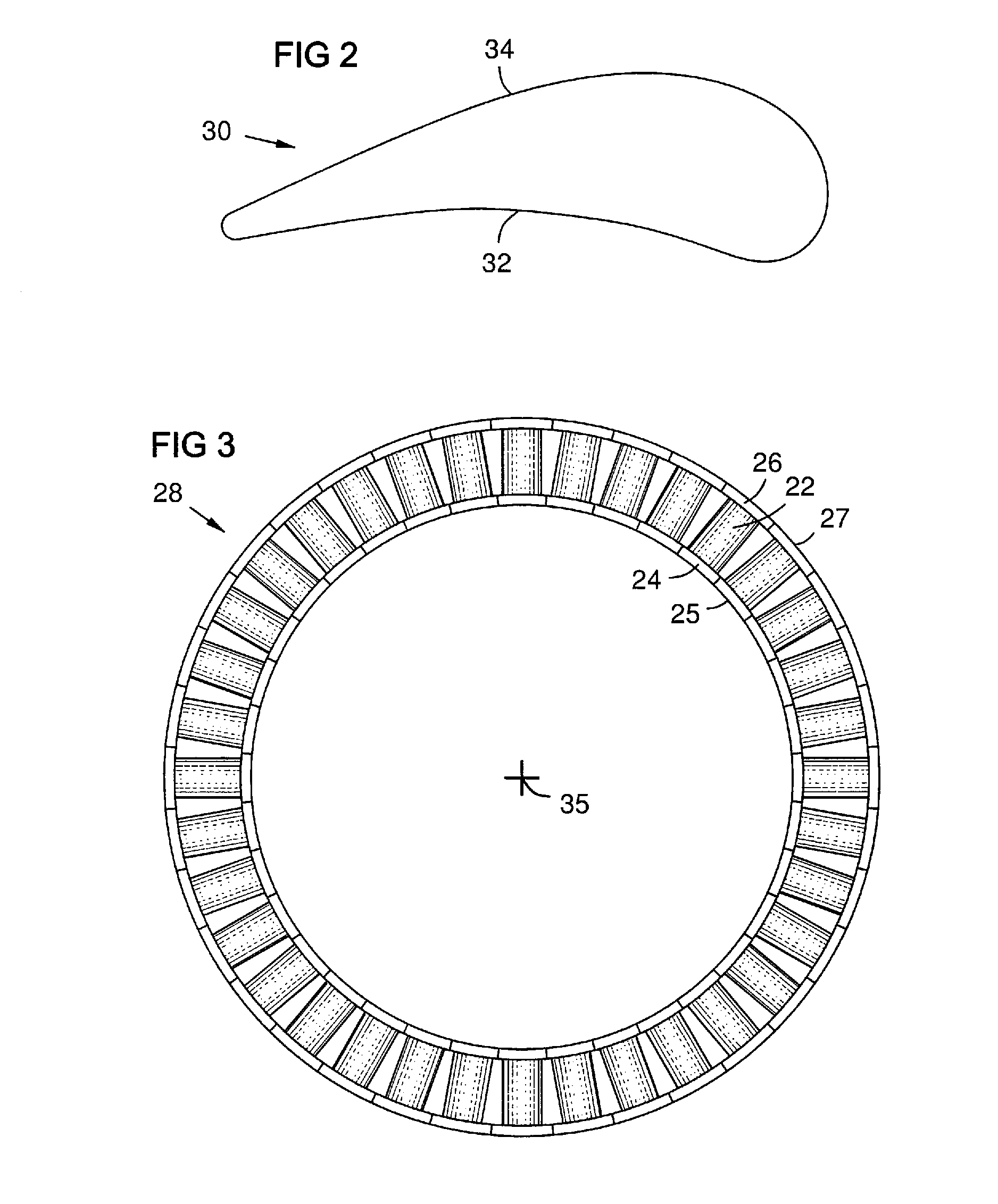
[0012]FIG. 1 shows a gas turbine vane assembly 20 comprising a vane airfoil 22 with inner and outer ends attached to respective inner and outer vane platforms 24, 26. Each vane airfoil 22 has a pressure side 32 and a suction side 34. This is shown in a transverse sectional profile 30 of a vane in FIG. 2. The vane assembly 20 is installed in a circular array 28 of such vane assemblies as in FIG. 3, in which each platform 24, 26 contacts two adjacent platforms along opposite circumferential sides 36, 38 of the platform. This results in circular arrays of adjacent inner and outer platforms forming respective inner and outer shroud rings 25, 27 that channel the hot working gas 40 of the turbine between them and across the vanes 22. The outer platforms 26 may be attached to a vane carrier ring as known (not shown). Each platform has a working gas face 42, 44 and a cooled side or face 46, 48 opposite the working gas face. A coolant 50 such as air is directed to the cooled side 48 of the o...


PUM

PropertyMeasurementUnit
Pressureaaaaaaaaaa

Abstract

Protective insert plates (54, 56) installed on a working gas face (42) of a turbine vane platform (26) provide replaceable portions of a turbine shroud for improved maintenance. The plates act as tiles, and may be formed of ceramic materials for thermal protection. Two cages (58, 60) in the vane platform slidably receive the two insert plates (54, 56) from opposite circumferential sides (36, 38) of the platform. The plates slide into the cages up to the pressure and suction sides (32, 34) of the vane airfoil (22). The plates may have proximal edges (62, 64) shaped to fit the respective pressure and suction sides of the vane airfoil. A retainer plate 66 may be attached to a flange (72) on the cooled face (48) of each platform, and may contact each insert plate with a locking device (74, 76) to prevent sliding of the plate in the cage.

Description

FIELD OF THE INVENTION[0001]The invention relates to components in the hot working gas path of a gas turbine, and particularly to turbine shroud surfaces on platforms of turbine vanes, including metal and ceramic matrix composite (CMC) surfaces.BACKGROUND OF THE INVENTION[0002]Gas turbines have a compressor assembly, a combustor assembly, and a turbine assembly. The compressor compresses ambient air, which is then channeled into the combustor, where it is mixed with a fuel. The fuel and compressed air mixture is ignited, creating a working gas that may reach temperatures of 2500 to 2900° F. (1371 to 1593° C.). This gas then passes through the turbine assembly. The turbine assembly has a rotating shaft holding a plurality of circular arrays or “rows” of rotating blades. The turbine assembly also has a plurality of circular arrays of stationary vanes attached to a casing of the turbine. Each row of blades is preceded by a row of vanes to direct the working gas at an optimum angle agai...

Claims


Application Information

Patent Timeline
IPC IPC(8): F01D9/04
CPCF01D5/147F01D9/04F05D2240/11F05D2300/5024F05D2240/81F05D2300/603F05D2300/21
Inventor SCHIAVO, ANTHONY L.
Owner SIEMENS ENERGY INC
Why Eureka
Try Eureka