Compressor blade with forward sweep and dihedral

Active Publication Date: 2010-03-04
SIEMENS ENERGY INC
View PDF16 Cites 163 Cited by
  • Summary
  • Abstract
  • Description
  • Claims
  • Application Information

AI Technical Summary

Benefits of technology

[0005]In accordance with one aspect of the invention, a compressor airfoil is provided for pressurizing air inside a surrounding casing. The airfoil comprises laterally opposite pressure and suction sides joined together at chordally opposite leading and trailing edges and extending in span from a root to a tip. A radially inner portion and a radially outer portion of the airfoil are defined along the span. A leading edge aerodynamic sw

Problems solved by technology

However, prior art airfoil designs have generally not emphasized incorporating significant dihedral

Method used


Image

  • Compressor blade with forward sweep and dihedral
  • Compressor blade with forward sweep and dihedral
  • Compressor blade with forward sweep and dihedral

Examples


Embodiment Construction

[0024]In the following detailed description of the preferred embodiment, reference is made to the accompanying drawings that form a part hereof, and in which is shown by way of illustration, and not by way of limitation, a specific preferred embodiment in which the invention may be practiced. It is to be understood that other embodiments may be utilized and that changes may be made without departing from the spirit and scope of the present invention.

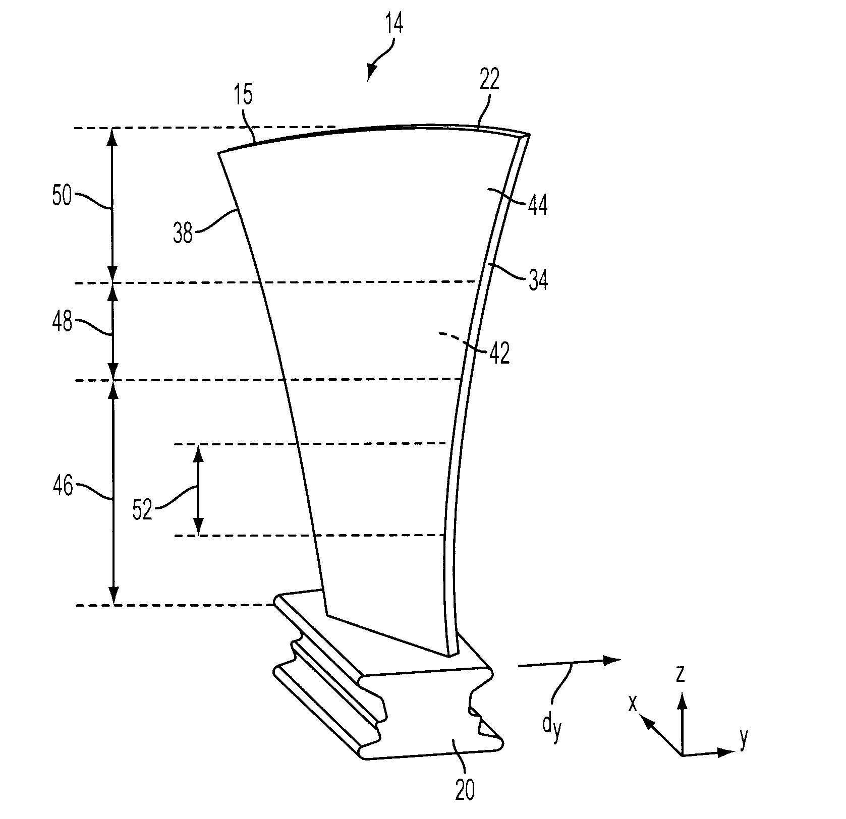
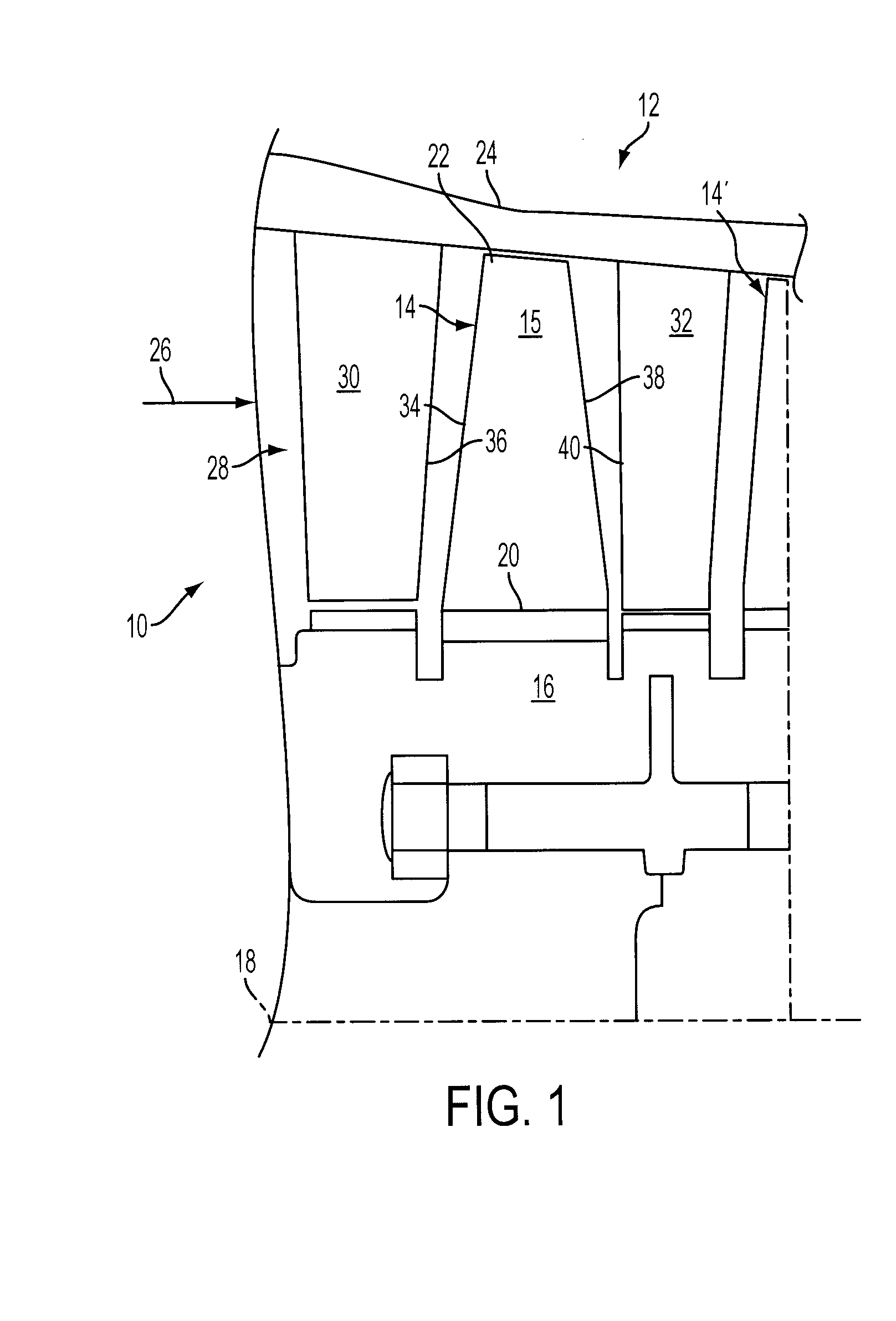
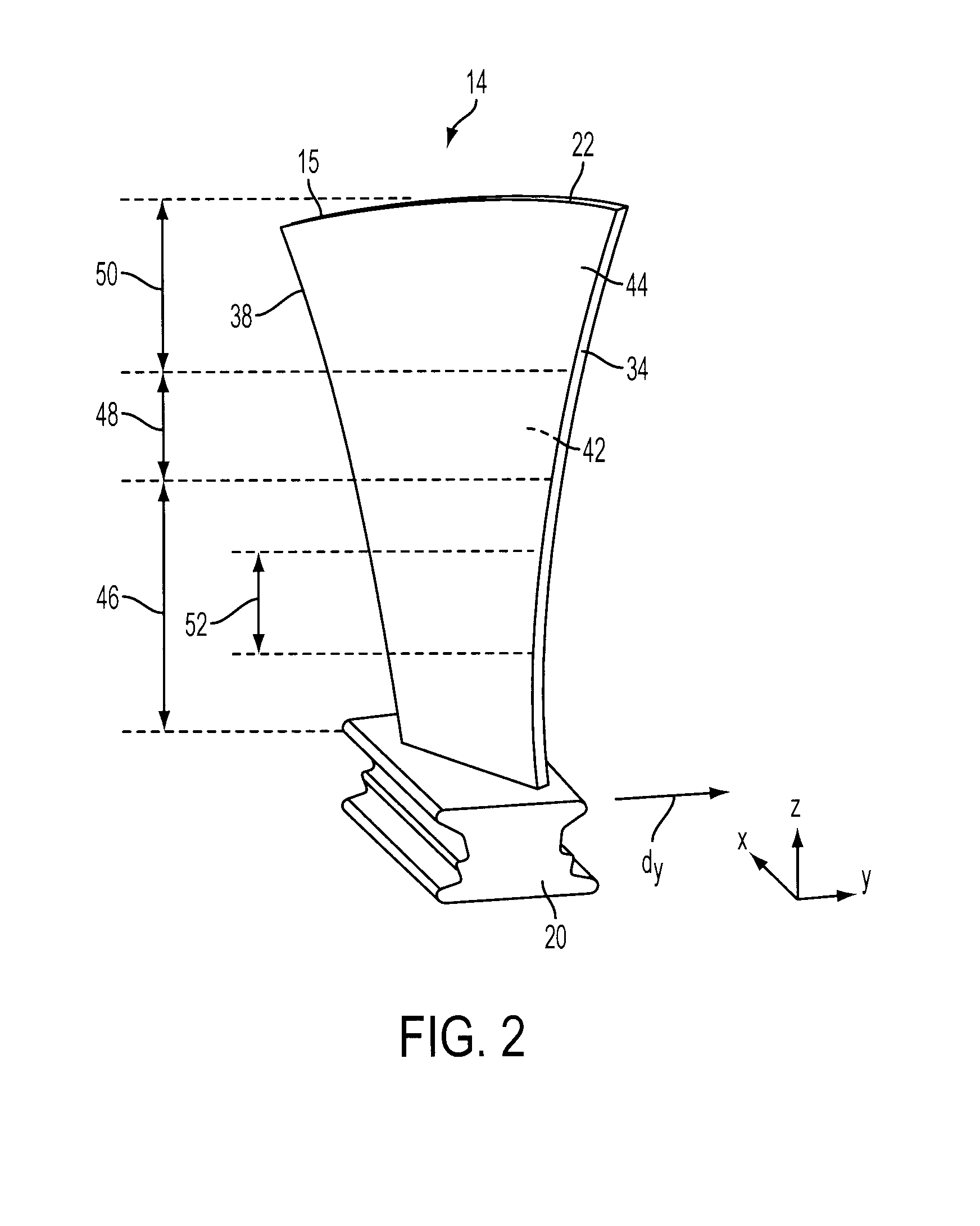
[0025]Referring to FIG. 1, portion of an exemplary compressor section 10 for a gas turbine engine 12 is shown in which a plurality of rotor or compressor blades 14 are supported in circumferentially extending rows around an annular hub 16 for rotation about a longitudinal axis centerline 18 of the turbine engine 12. Each of the blades 14 includes a root portion 20 attached to the hub 16, such as by the root portions 20 being formed with a fir-tree or dovetail shape (FIG. 2) for engagement within corresponding grooves in the hub 16, or by...


PUM


Abstract

An airfoil for use as rotor blades in compressors for turbomachines, such as gas turbine engines. The airfoil includes increased forward sweep and forward dihedral effective to reduce losses generated by interaction of tip clearance flow, secondary flows and passage shocks.

Description

FIELD OF THE INVENTION[0001]The invention relates generally to turbomachines and, more particularly, to airfoil shapes for use as rotor blades in compressors for turbomachines such as gas turbine engines.BACKGROUND OF THE INVENTION[0002]In a turbomachine, such as a gas turbine engine, air is pressurized in a compressor then mixed with fuel and burned in a combustor to generate hot combustion gases. The hot combustion gases are expanded within the turbine section where energy is extracted to power the compressor and to produce useful work, such as powering a propeller for an aircraft in flight or turning a generator to produce electricity. The hot combustion gas travels through a series of turbine stages. A turbine stage may include a row of stationary vanes followed by a row of rotating turbine blades, where the turbine blades extract energy from the hot combustion gas for powering the compressor and providing output power.[0003]In a multistage axial compressor, the cooperating rows...

Claims


Application Information

Patent Timeline
IPC IPC(8): F01D5/14
CPCF04D29/324Y02T50/673F05D2250/74F05D2220/3216Y02T50/60
Inventor OROSA, JOHNMONTGOMERY, MATTHEW
Owner SIEMENS ENERGY INC
Why Eureka
Try Eureka