Method of setting wireless link, wireless communication device and wireless system

a wireless communication device and wireless system technology, applied in the direction of power management, climate sustainability, sustainable buildings, etc., can solve the problems of affecting the immediate effect, requiring a longer connection time, and requiring a lot of power consumption on the advertising side that continues to transmit the adv_ind packets

Inactive Publication Date: 2010-03-04
KK TOSHIBA
View PDF16 Cites 67 Cited by
  • Summary
  • Abstract
  • Description
  • Claims
  • Application Information

AI Technical Summary

Benefits of technology

[0019]Another aspect of the present invention is a method of setting a wireless link in a wireless system between a first wireless device and a second wireless device, wherein: the first wireless device including an extremely low-power receiver turns on the first wireless device and continues broadcast transmission of a packet periodically without a transmission pause until reception of a response packet from the second wireless device when the extremely low-power receiver receiv...

Problems solved by technology

However, there are problems in processing CONNECTION setting by the ULP Bluetooth(R) communication technique, as described below.
Therefore, the advertiser side that contin...

Method used


Image

  • Method of setting wireless link, wireless communication device and wireless system
  • Method of setting wireless link, wireless communication device and wireless system
  • Method of setting wireless link, wireless communication device and wireless system

Examples


first embodiment

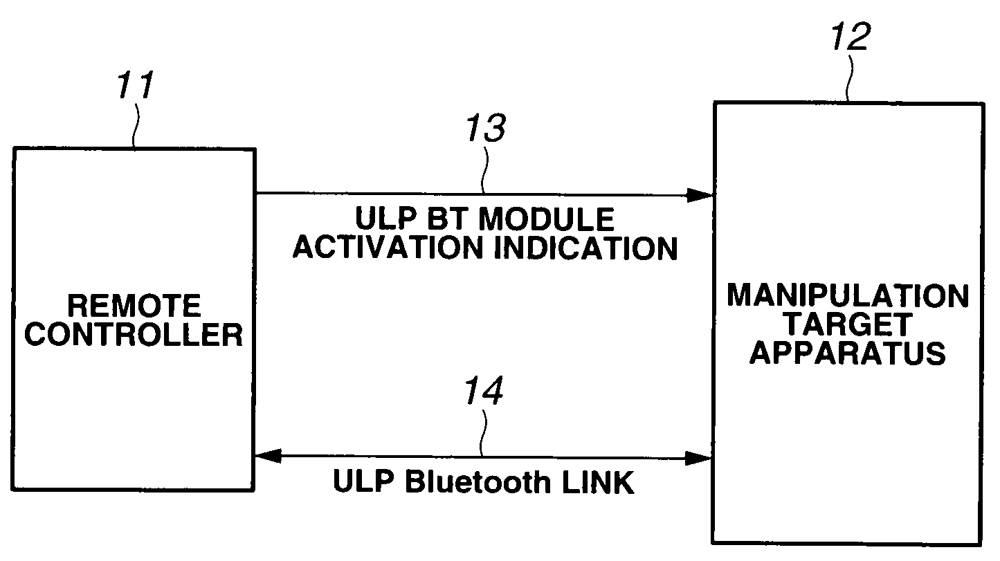
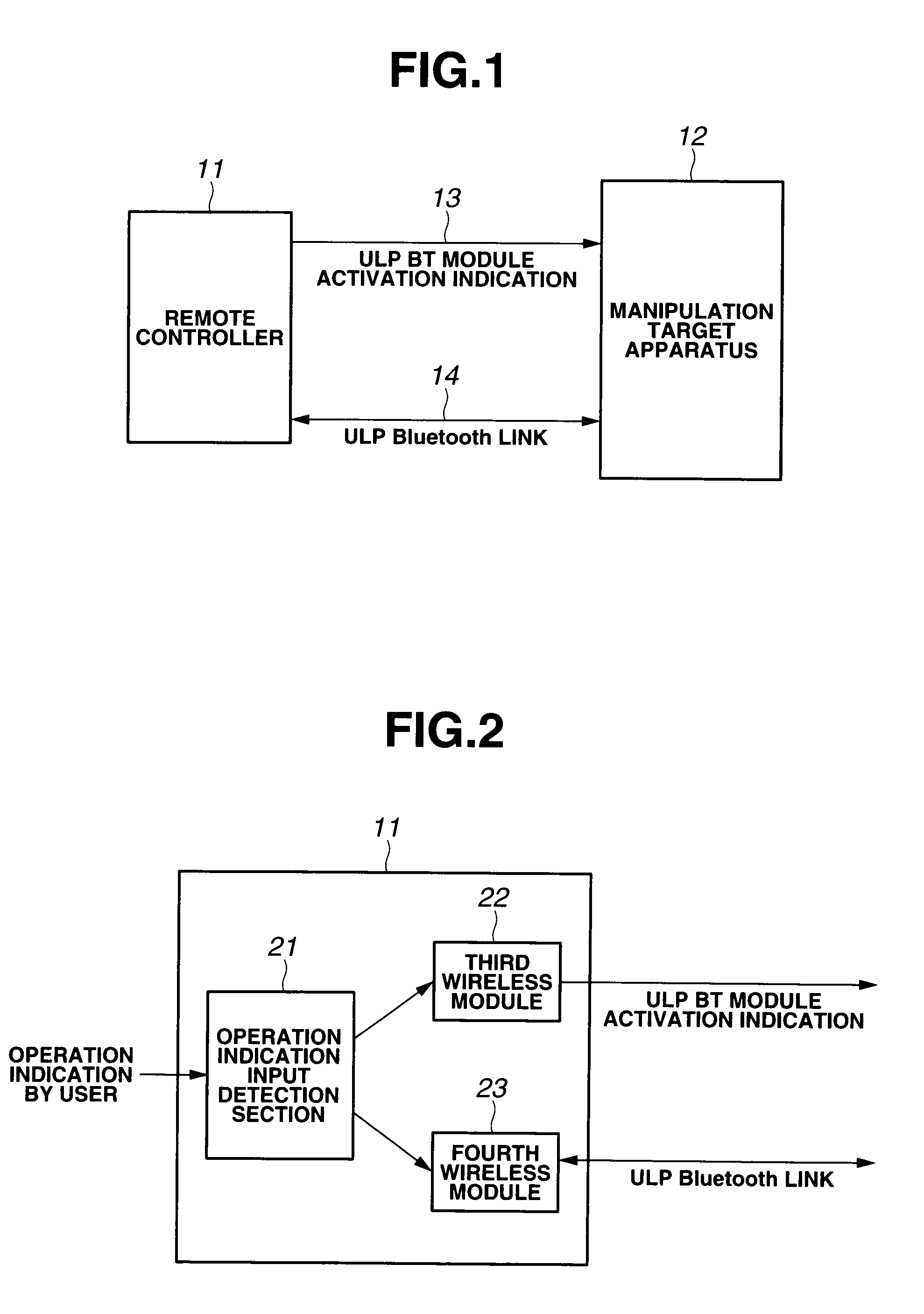
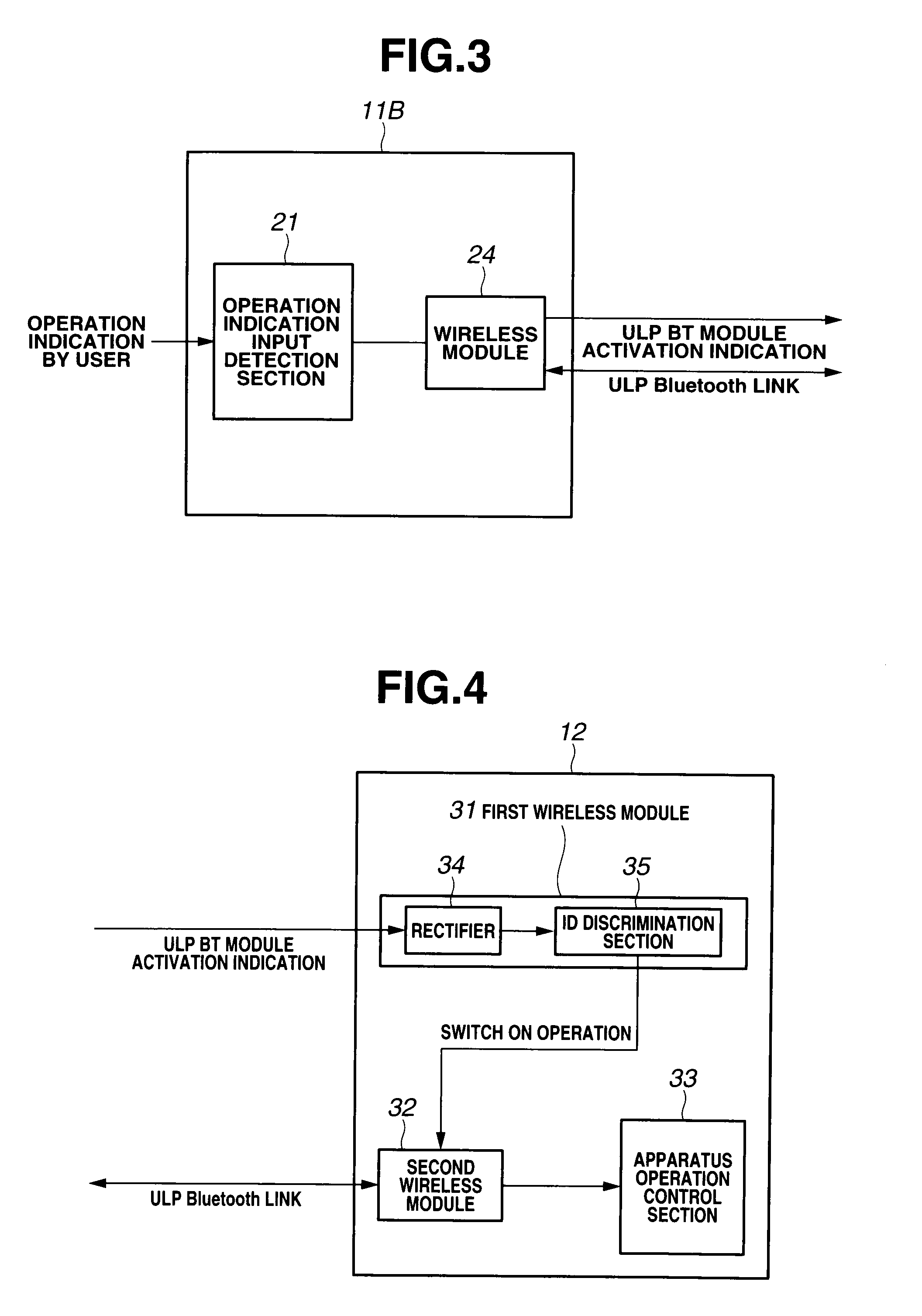
[0053]FIG. 1 is a block diagram schematically showing a wireless system according to the first embodiment of the present invention. FIG. 2 is a block diagram showing one configuration example of a remote controller as a second wireless device in FIG. 1. FIG. 3 is a block diagram showing another configuration example of the remote controller as the second wireless device in FIG. 1. FIG. 4 is a block diagram showing a configuration example of a manipulation target apparatus as a first wireless device in FIG. 1. FIG. 5 is a block diagram illustrating a configuration example of a rectifier in the manipulation target apparatus shown in FIG. 4. FIG. 6 is a diagram showing a processing flow until communication is initiated with a ULP Bluetooth(R) link being established between the second wireless device and the first wireless device. FIG. 7 is a flowchart illustrating operation by a remote controller side in the processing shown in FIG. 6. FIG. 8 is a flowchart illustrating operation by a ...

second embodiment

[0086]FIG. 9 is a block diagram schematically showing a wireless system according to a second embodiment of the present invention. FIG. 10 is a block diagram showing one configuration example of a remote controller as a second wireless device in FIG. 9. FIG. 11 is a block diagram showing another configuration example of the remote controller as the second wireless device in FIG. 9. FIG. 12 is a block diagram showing a configuration example of a manipulation target apparatus as a first wireless device in FIG. 9. FIG. 13 is a diagram showing one example of a processing flow until communication is initiated with a Bluetooth(R) link being established between the second wireless device and the first wireless device. FIG. 14 is a diagram showing another example of the processing flow until communication is initiated with a Bluetooth(R) link being established between the second wireless device and the first wireless device. In the second embodiment, the present invention is applied to a wi...

third embodiment

[0109]FIG. 15 is a block diagram schematically showing a wireless system according to a third embodiment of the present invention.

[0110]In the first embodiment, a wireless module in a manipulation target apparatus is provided with an extremely low-power receiver so that a remote controller gives a ULP BT module activation indication to the manipulation target apparatus based on an operation indication from the outside in ULP Bluetooth(R) communication between two wireless devices. In the present embodiment, a wireless module in a remote controller is provided with an extremely low-power receiver so that a manipulation target apparatus gives a ULP BT module activation indication to a remote controller based on an operation indication from the outside.

[0111]As shown in FIG. 15, according to the present embodiment, a manipulation target apparatus 71 can establish the following to a remote controller 72:

[0112](1) communication to instruct ULP Bluetooth(R) communication activation (a ULP...


PUM


Abstract

A method of setting a wireless link is provided between a first wireless device and a second wireless device in a wireless system. The first wireless device includes an extremely low-power receiver. When the extremely low-power receiver receives a predetermined wireless signal, the receiver turns on the first wireless device, and continues broadcast transmission of a packet periodically without a transmission pause until receiving a response packet from the second wireless device.

Description

CROSS-REFERENCE TO RELATED APPLICATIONS[0001]This application is based upon and claims the benefit of priority from the prior Japanese Patent Application No. 2008-224784 filed in Japan on Sep. 2, 2008 and Japanese Patent Application No. 2009-097352 filed in Japan on Apr. 13, 2009; the entire contents of which are incorporated herein by reference.BACKGROUND OF THE INVENTION[0002]1. Field of the Invention[0003]The present invention relates to a method of setting a wireless link, a wireless communication device and a wireless system for manipulation of a manipulation target apparatus such as a TV receiver by a remote controller via Bluetooth(R) communication or Bluetooth(R) ULP communication.[0004]2. Description of Related Art[0005]Traditionally, a remote controller system was proposed that used wireless technology as in Japanese Patent Application Laid-Open Publication No. 10-276480, for example. In particular, this patent document discloses that a remote controller mode as well as a ...

Claims


Application Information

Patent Timeline
IPC IPC(8): H04B7/00
CPCH04W52/286Y02B60/50H04W52/50
Inventor YAMATO, KATSUMISAKAMOTO, TAKAFUMIUMEDA, TOSHIYUKIOTAKA, SHOJIMERA, KEISUKENISHIMURA, HIROSHIMAKARI, HIROO
Owner KK TOSHIBA
Why Eureka
Try Eureka