
Plug-in connector for medical tubes

a technology for plug-in connectors and medical tubes, which is applied in the direction of hose connections, catheters, angiography, etc., can solve the problems of attenuation of measured signals, complicated design of plug-in connectors on the whole, inaccurate measurement, etc., and achieves simple manufacturing and handling, reliable connection of plug-in parts, and simple effect of manufacture and handling

Active Publication Date: 2010-03-04
DRAGERWERK AG
View PDF15 Cites 7 Cited by
  • Summary
  • Abstract
  • Description
  • Claims
  • Application Information

AI Technical Summary

Benefits of technology

[0006]The object of the present invention is to overcome the drawbacks shown in the state of the art and to provide a plug-in connector that can be both manufactured and handled in a simple manner and guarantees reliable connection of the plug-in parts.
[0008]A more reliable plug-type connection that can be separated in a simple manner is created in this manner.
[0011]The internal diameter of the elastic section of the second plug-in part is advantageously equal to the internal diameter of the inner passage of the first plug-in part and to the internal diameter of a connection tube. The constant lumen resulting herefrom guarantees low-loss transmission of sound waves in the application of the plug-in connector in a noninvasive blood pressure measuring system. Better signal quality can now be achieved and the blood pressure of a patient can be detected more accurately. An application of the plug-in connector according to the present invention for a noninvasive blood pressure measuring system thus makes it possible to increase patient safety.

Problems solved by technology

This makes the design of the plug-in connector on the whole complicated, because tight connections must be established both between the tubes and the respective plug-in part and between the respective plug-in parts themselves.
Different diameters of the passage opening of the plug-in connectors may lead to attenuation of the measured signal and hence to an inaccurate measurement result during the transmission of the measured signal especially during a noninvasive blood pressure measurement.

Method used


Image

  • Plug-in connector for medical tubes
  • Plug-in connector for medical tubes
  • Plug-in connector for medical tubes

Examples


Embodiment Construction

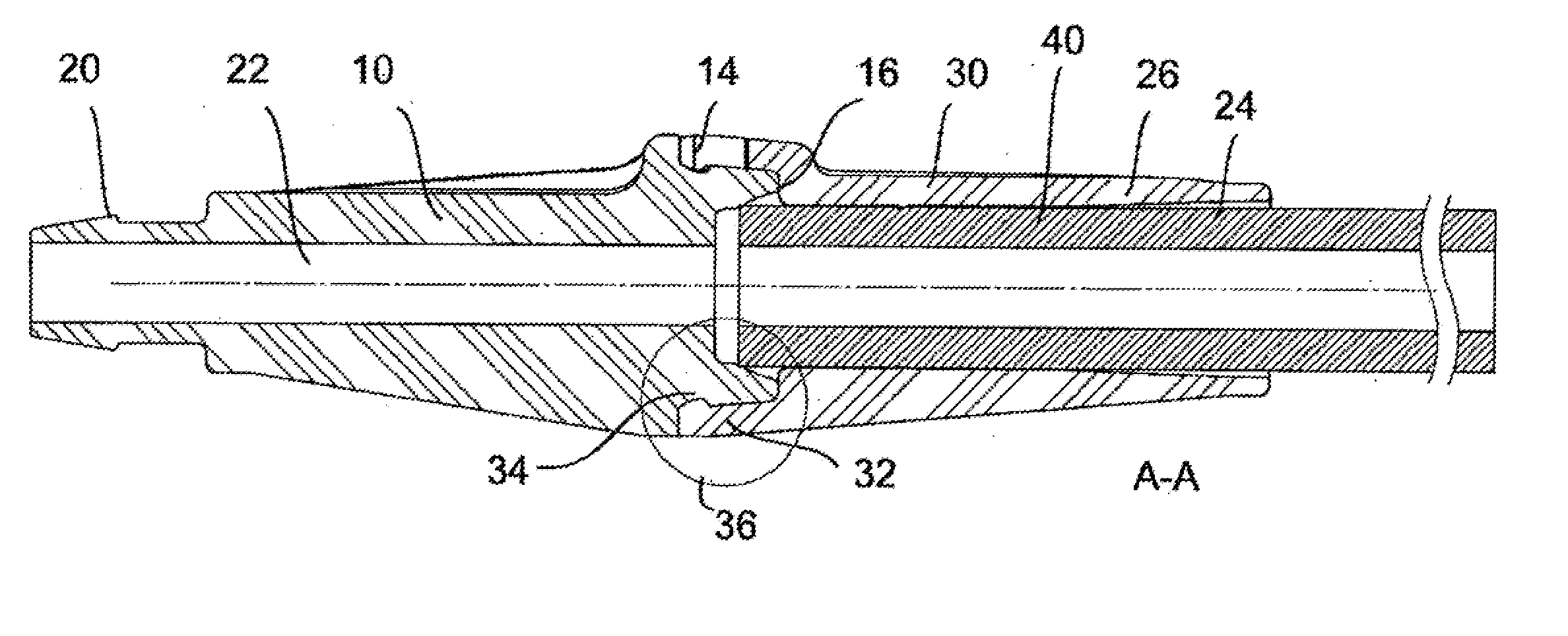
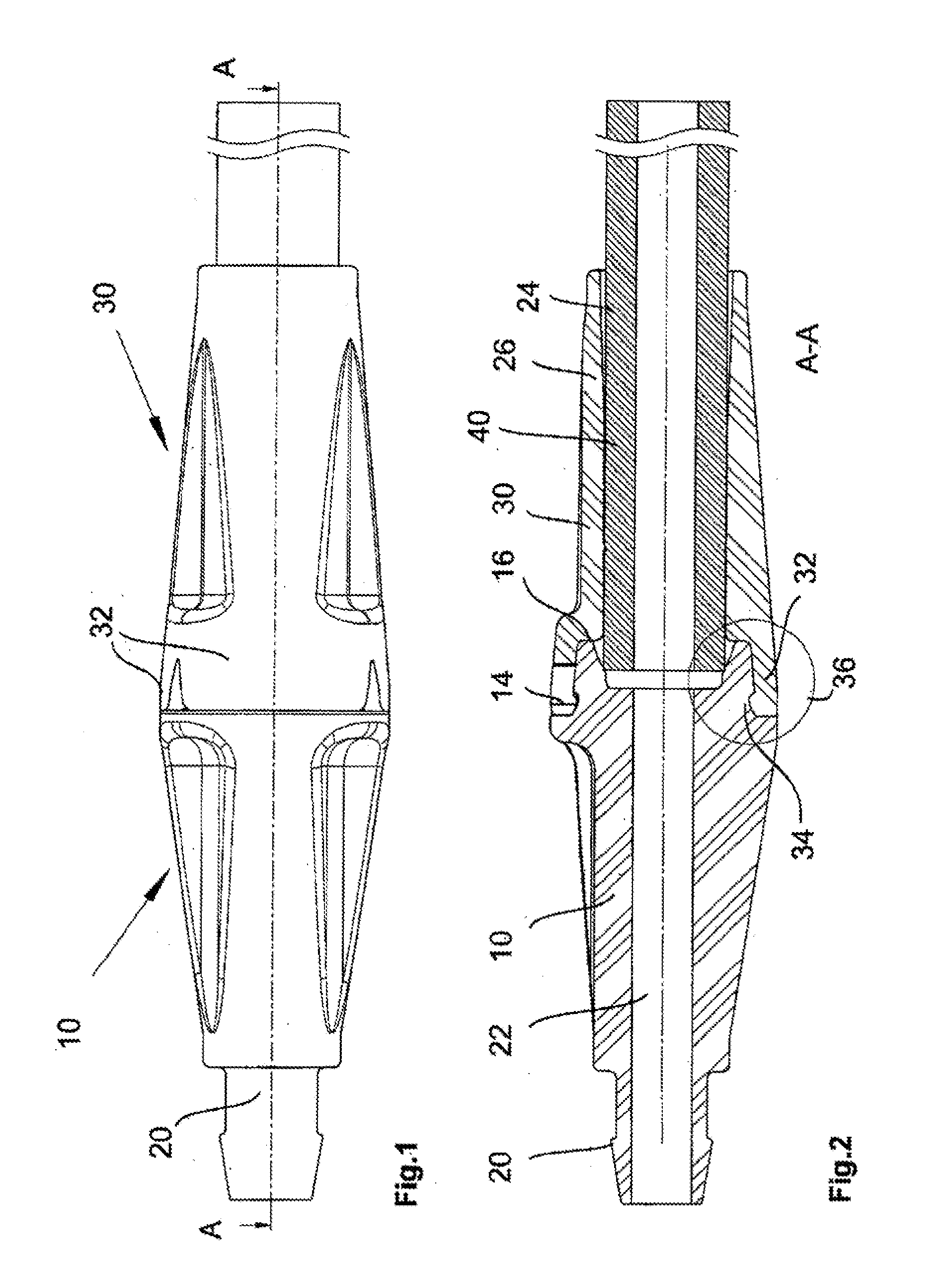
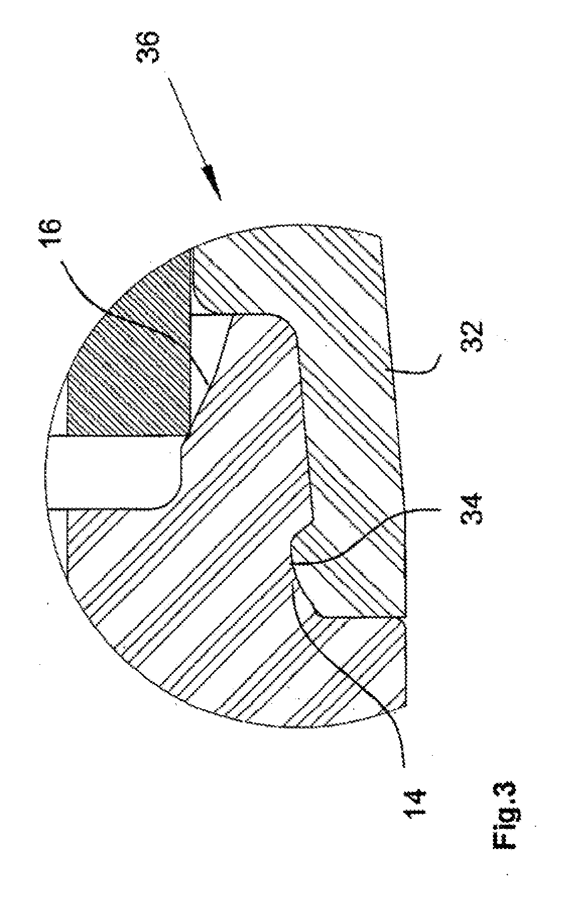
[0022]Referring to the drawings in particular, the plug-in connector shown in FIGS. 1 and 2 has a first plug-in part 10 and a second plug-in part 30, which extends around the outer surface of the first plug-in part 10 with its front end. The end of the second plug-in part 30 facing a connection area 36 has snap-in elements 32, which are designed as snap-in hooks which protrude forwardly in the axial direction in the connection area 36 and have radially inwardly pointing projections 34 at their protruding end. The projections 34 are provided for meshing with a complementary recess 14 on the outer surface of one plug-in part 10. When the plug-in parts 10 and 30 are pushed into one another, the projections 34 slide on the front outer surface of the front end of the first plug-in part 10, which surface expands slightly conically in this area, as a result of which the snap-in elements 32 are bent elastically outwardly. When the projections 34 of the snap-in elements 32 reach the recess 1...


PUM


Abstract

A plug-in connector for medical tubes is provided with a first plug-in part (10) and a second plug-in part (30), wherein the second plug-in part (30) extends around the first plug-in part (10) in the plugged-together state. The second plug-in part (30) has at least one forwardly protruding snap-in element (32), which has at its front end at least one inwardly protruding projection (34). The inwardly protruding projection is provided for meshing (engaging) with a complementary recess (14) in the outer surface of the first plug-in part (10) in order to thus hold the second plug-in part (30) fixed in the axial direction on the first plug-in part (10) due to the projection (34) meshing with the recess (14). Both plug-in parts (10,30) have a central passage opening (22, 24) each, wherein one plug-in part (10, 30) has an end area (16) expanding towards the outlet opening in a connection area (36) and the other plug-in part (10, 30) is connected to an elastic section (40), which is arranged in its interior and which protrudes into the connection area (36), so that the front end of the elastic section (40) is pressed into contact with the expanded end area (16) of the opposite plug-in part (10, 30). The projection (34) of the at least one snap-in element (32) maintains the second plug-in part (30) meshed with the first plug-in part (10), so that the elastic section (40) exerts a sealing function due to the pressure on the expanding end area (16).

Description

CROSS REFERENCE TO RELATED APPLICATIONS[0001]This application claims the benefit of priority under 35 U.S.C. §119 of European Patent Application EP 08 2008 163 270.5 filed Aug. 29, 2008, the entire contents of which are incorporated herein by reference.FIELD OF THE INVENTION[0002]The present invention pertains to a plug-in connector for medical tubes.BACKGROUND OF THE INVENTION[0003]Medical plug-in connectors are used, for example, to connect a sphygmomanometer cuff to a blood pressure analysis unit in noninvasive blood pressure measurement applications.[0004]A plug-in connector for pressure and vacuum tubes is known from U.S. Pat. No. 3,640,552. The prior-art connector has an inner plug-in part and an outer plug-in part, which extends around a front end area of the inner plug-in part in the attached state and is provided with protruding elastic snap-in hooks with radially inwardly protruding projections, which are bent at first radially outwardly when pushed over the inner plug-in ...

Claims


Application Information

Patent Timeline
IPC IPC(8): A61B5/022F16L33/16
CPCA61M39/1011F16L37/0925A61M39/12
Inventor GRABL, THOMASKOULECHOV, KIRILL
Owner DRAGERWERK AG
Learn More