Acoustic Beam Forming in Phased Arrays Including Large Numbers of Transducer Elements

a phased array and transducer technology, applied in piezoelectric/electrostrictive devices, sound producing devices, surgical instruments for heating, etc., can solve the problems of complex system and high cost of implementation

Inactive Publication Date: 2010-03-04
INSIGHTEC
View PDF98 Cites 47 Cited by
  • Summary
  • Abstract
  • Description
  • Claims
  • Application Information

AI Technical Summary

Benefits of technology

[0010]Using a switch with “m” drive channels to control drive signals provided to a relatively large number of “n” transducer elements may substantially minimize the complexity of the system, since relatively few drive channels may be needed for a relatively large number of transducer elements. It may also allow complex phase patterns to be created in a sub-set of transducer elements or using the entire transducer array, while using a limited number of input drive channels. In addition, because a limited number of drive channels deliver power to a relatively large number of transducer elements, the drive channels may be loaded substantially evenly, as desired for statistically even phase distribution.
[0018]Preferably, each of the “m” sets of drive signals is connected to a plurality of the “n” transducer elements, whereby each of the transducer elements is connected to one of the sets of drive signals. Each of the transducer elements may be connected to one of the sets of drive signals at least partially based upon phase shift values assigned to the transducer elements based upon at least one of a size, shape, and / or location of a focal zone within the target region, to compensate for tissue aberrations that may occur along an acoustic path from each of the transducer elements to the focal zone, to set equal power distribution between drive channels, and / or to compensate for impedance variations between the transducer elements.

Problems solved by technology

The problem with providing so many transducer elements is that individual sets of drive signals must be delivered to each transducer element in order for the transducer elements to transmit acoustic energy.
The resulting system would be complicated and expensive to implement.

Method used


Image

  • Acoustic Beam Forming in Phased Arrays Including Large Numbers of Transducer Elements
  • Acoustic Beam Forming in Phased Arrays Including Large Numbers of Transducer Elements
  • Acoustic Beam Forming in Phased Arrays Including Large Numbers of Transducer Elements

Examples


Embodiment Construction

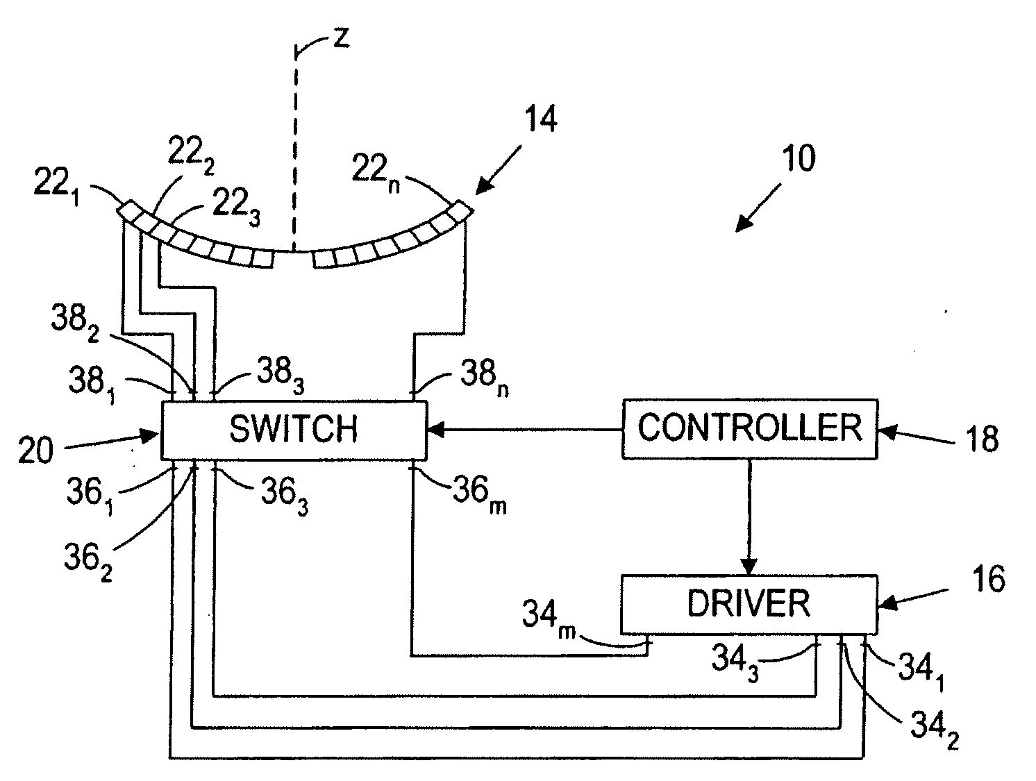
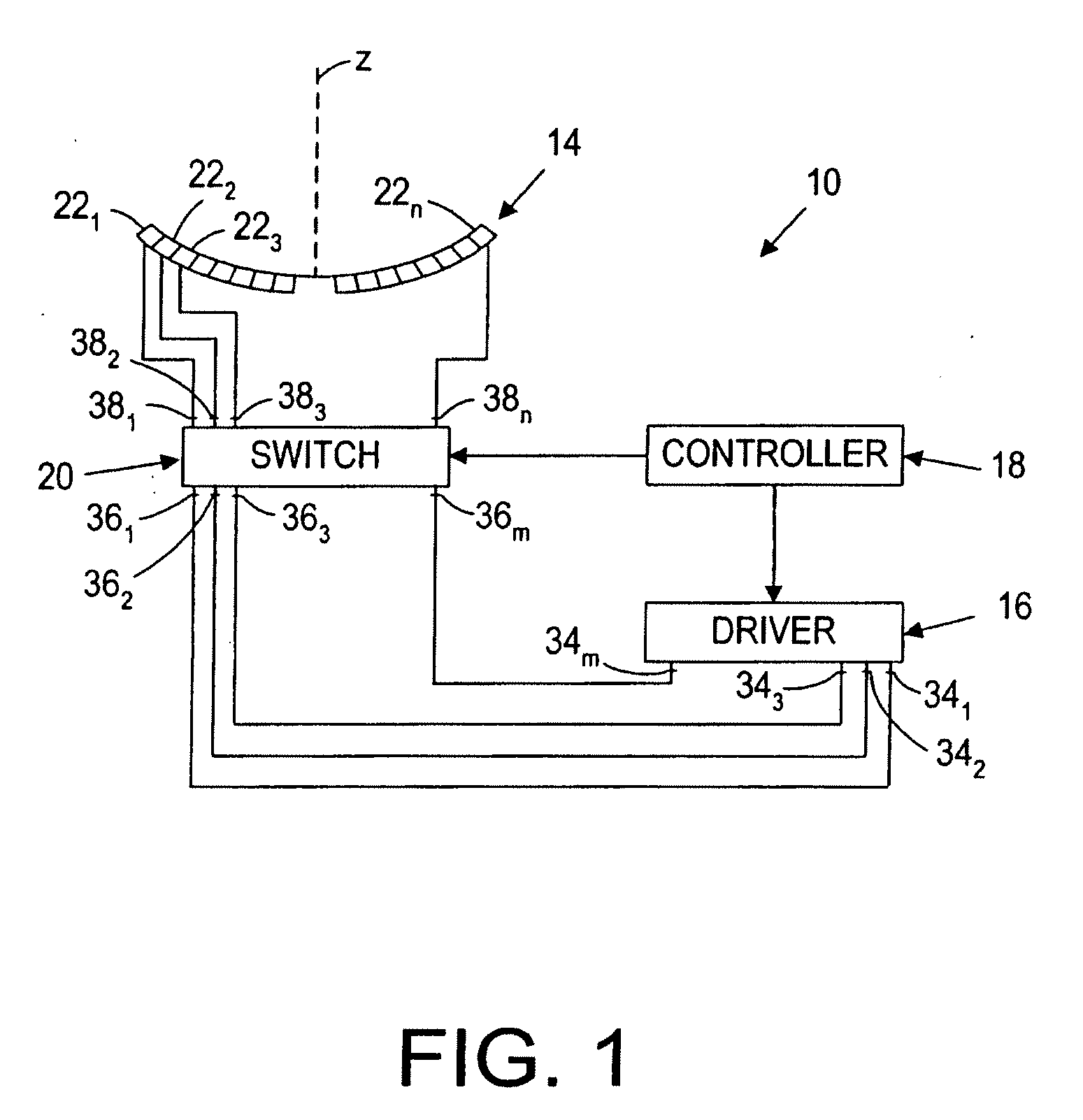
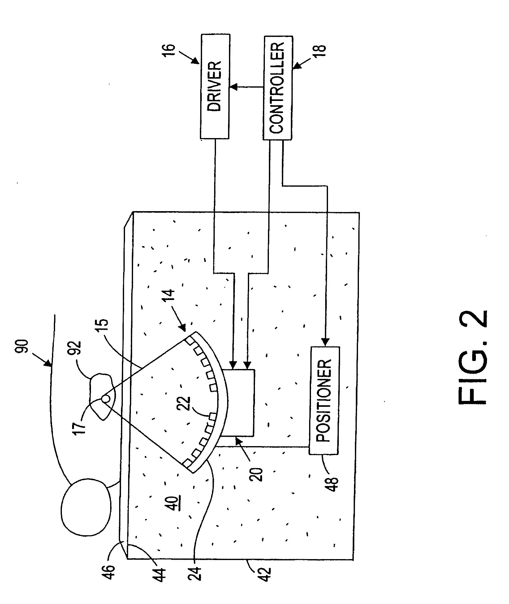
[0024]Turning now to the drawings, FIGS. 1 and 2 depict an exemplary embodiment of a focused ultrasound system 10, including a transducer array 14, a driver 16, a controller 18, and a switch 20, in accordance with the present invention. As best seen in FIG. 2, the transducer array 14 may deliver acoustic energy represented by acoustic beam 15 into a target region 92, e.g., a benign or malignant tumor or other tissue volume, within a patient's body 90, to ablate or otherwise treat tissue within the target region 92. As explained further below, the switch 20 connects the transducer array 14 to the driver 16 and / or to the controller 18 in order to steer and / or focus the acoustic energy transmitted by the transducer array 14 in a desired manner.

[0025]With particular reference to FIG. 1, the transducer array 14 generally includes multiple transducer elements 22 arranged in a pattern on a substrate 24. The substrate 24 may be a frame, a planar or curved structure, and the like, onto which...


PUM


Abstract

A focused ultrasound system includes a transducer array, a controller for providing drive signals to the transducer array, and a switch. The transducer array includes a plurality of “n” transducer elements, and the controller includes a plurality of “m” output channels providing sets of drive signals having respective phase shift values, “m” being less than “n.” The switch is coupled to the output channels of the controller and to the transducer elements, and is configured for connecting the output channels to respective transducer elements. The controller may assign the transducer elements to respective output channels based upon a size and / or shape of a desired focal zone within the target region, to steer or otherwise move a location of the focal zone, and / or to compensate for tissue aberrations caused by tissue between the transducer array and the focal zone, geometric tolerances and / or impedance variations of the transducer elements.

Description

FIELD OF THE INVENTION[0001]The present invention relates generally to systems and methods for delivering acoustic energy into a body, and more particularly to systems and methods for focusing acoustic energy transmitted from a transducer array including a large number of transducer elements.BACKGROUND[0002]Focused ultrasound systems have been suggested for delivering acoustic energy into a tissue region within a patient, such as a cancerous or benign tumor, to coagulate or otherwise treat the tissue region with thermal energy. For example, a piezoelectric transducer located outside the patient's body may be used to focus high intensity acoustic waves, such as ultrasonic waves (acoustic waves with a frequency greater than about twenty kilohertz (20 kHz)), at an internal tissue region of a patient to treat the tissue region. The acoustic waves may be used to ablate a tumor, thereby eliminating the need for invasive surgery. Such an acoustic transducer system is disclosed in U.S. Pat....

Claims


Application Information

Patent Timeline
Patent Type & Authority Applications(United States)
IPC IPC(8): A61N7/00A61B18/04G10K9/125H01L41/09A61N7/02G10K11/34
CPCA61N7/02A61N2007/0065G10K11/346A61N2007/0091A61N2007/0095A61N2007/0078
Inventor VORTMAN, KOBIVITEK, SHUKIEZION, AVNER
Owner INSIGHTEC
Why Eureka
Try Eureka