

Trans-corneal shunt and method
- Summary
- Abstract
- Description
- Claims
- Application Information
AI Technical Summary
Benefits of technology
Problems solved by technology
Method used
Image

Examples
Embodiment Construction
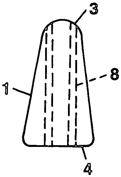
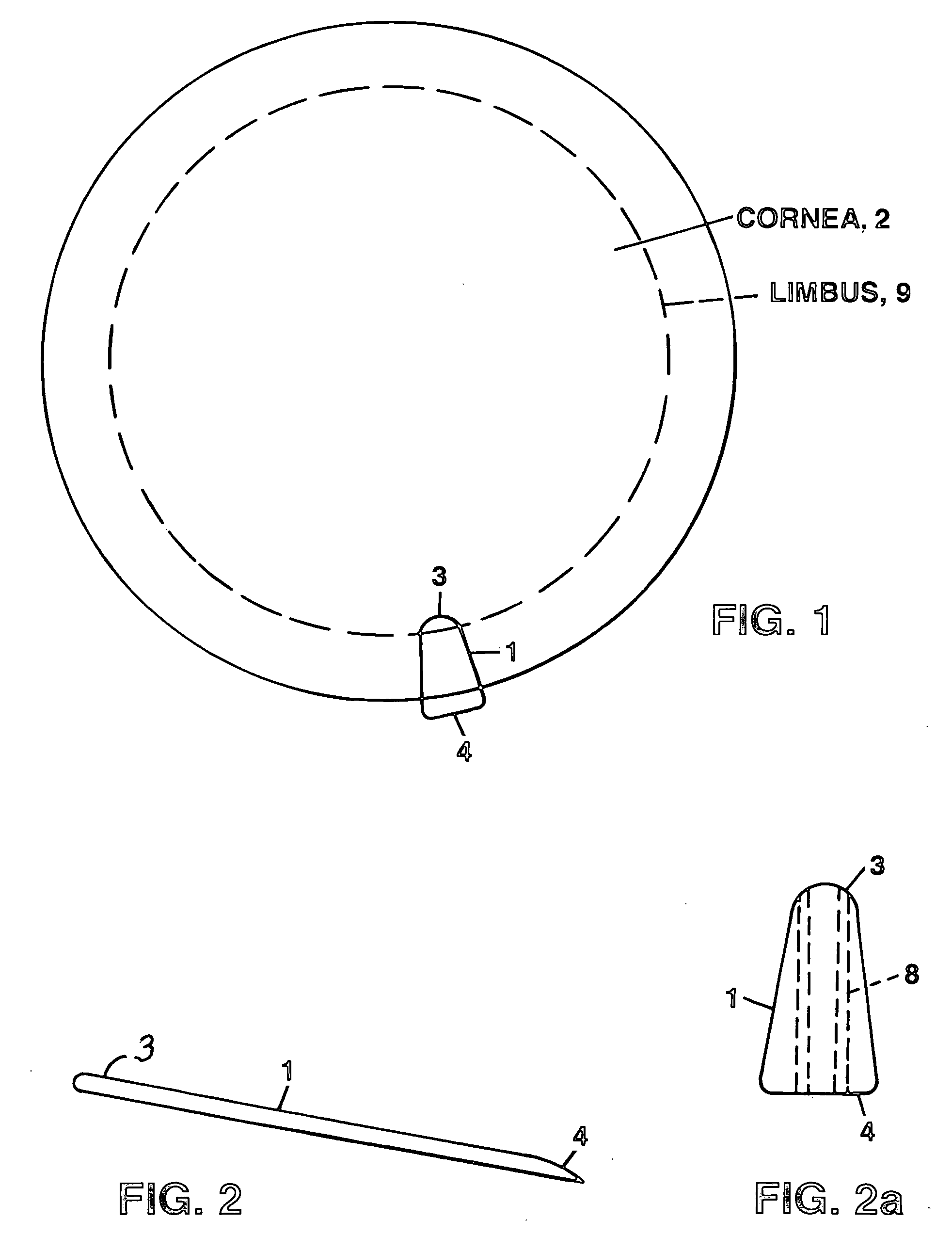
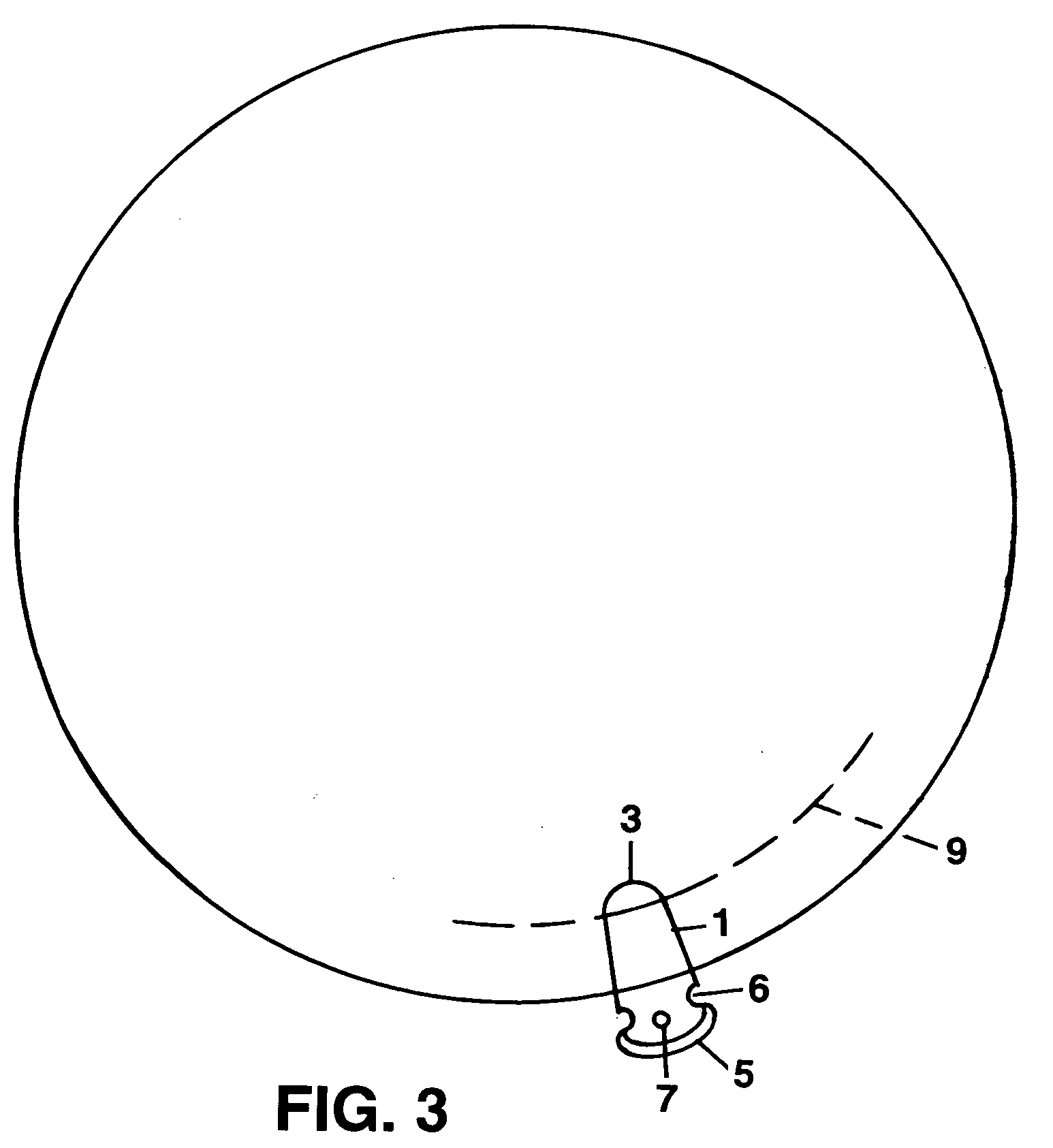
[0007]A thin flat trans-corneal shunt, having no cap or footplate, is inserted into the cornea through a self-sealing incision made by a keratome surgical knife. Extremely small tunnels or pores are formed within the thin flat trans-corneal shunt for transporting aqueous fluid from the anterior of the eye to the tear film on the surface of the eye while deterring bacteria from entering the eye. Fixation means are provided for maintaining the shunt in position upon the cornea by enabling a suture to co-act with a hole(S) or notch formed within the shunt. Additionally the shunt can be tapered for preventing an unacceptable degree of intrusion of the shunt into the anterior portion of the eye. Also, the trailing edge portion of the shunt is wide relative to other portions of the shunt, thereby facilitating grasping of the shunt when desired for removal from the cornea.
BRIEF DESCRIPTION OF THE DRAWINGS
[0008]Other features of the invention may become more apparent upon study of the follo...
PUM
 Abstract
Description
Claims
Application Information