Automated software testing environment

Inactive Publication Date: 2010-03-04
SONY CORP
View PDF4 Cites 29 Cited by
  • Summary
  • Abstract
  • Description
  • Claims
  • Application Information

AI Technical Summary

Benefits of technology

[0016]As a result of the testing system and methodology described herein, developers are provided with information about the state which the DUT had at the time that a problem occurred. Moreover, developers are provided with visu

Problems solved by technology

Unfortunately, these steps are manual by nature and time consuming.
The tester's perspective usually does not aid developers in pinpointing the technical source of the problem/defect since the tester's perspective is generally non-technical in nature.
For example, a tester may note a problem regarding a portion of the screen that displays a graphical element.
However, a noted problem/defect in displaying a graphical element on a portion of a display does not provide developers with full technical information needed to troubleshoot the defective unit, e.g., the state of the processor, the contents of memory, etc., that coincide with this problem/defect.
Moreover, reliance on the tester's perspective does not guarantee that the problem/defect can be duplicated.
For example, the problem/defect may have occurred in

Method used


Image

  • Automated software testing environment
  • Automated software testing environment
  • Automated software testing environment

Examples


Example

[0022]Reference will now be made in detail to embodiments of the present invention, examples of which are illustrated in the accompanying drawings. While the invention will be described in conjunction with these embodiments, it will be understood that they are not intended to limit the invention to these embodiments. On the contrary, the invention is intended to cover alternatives, modifications and equivalents, which may be included within the spirit and scope of the invention as defined by the appended claims Furthermore, in the following detailed description of the present invention, numerous specific details are set forth in order to provide a thorough understanding of the present invention. However, it will be evident to one of ordinary skill in the art that the present invention may be practiced without these specific details. In other instances, well known methods, procedures, components, and circuits have not been described in detail as not to unnecessarily obscure aspects o...


PUM


Abstract

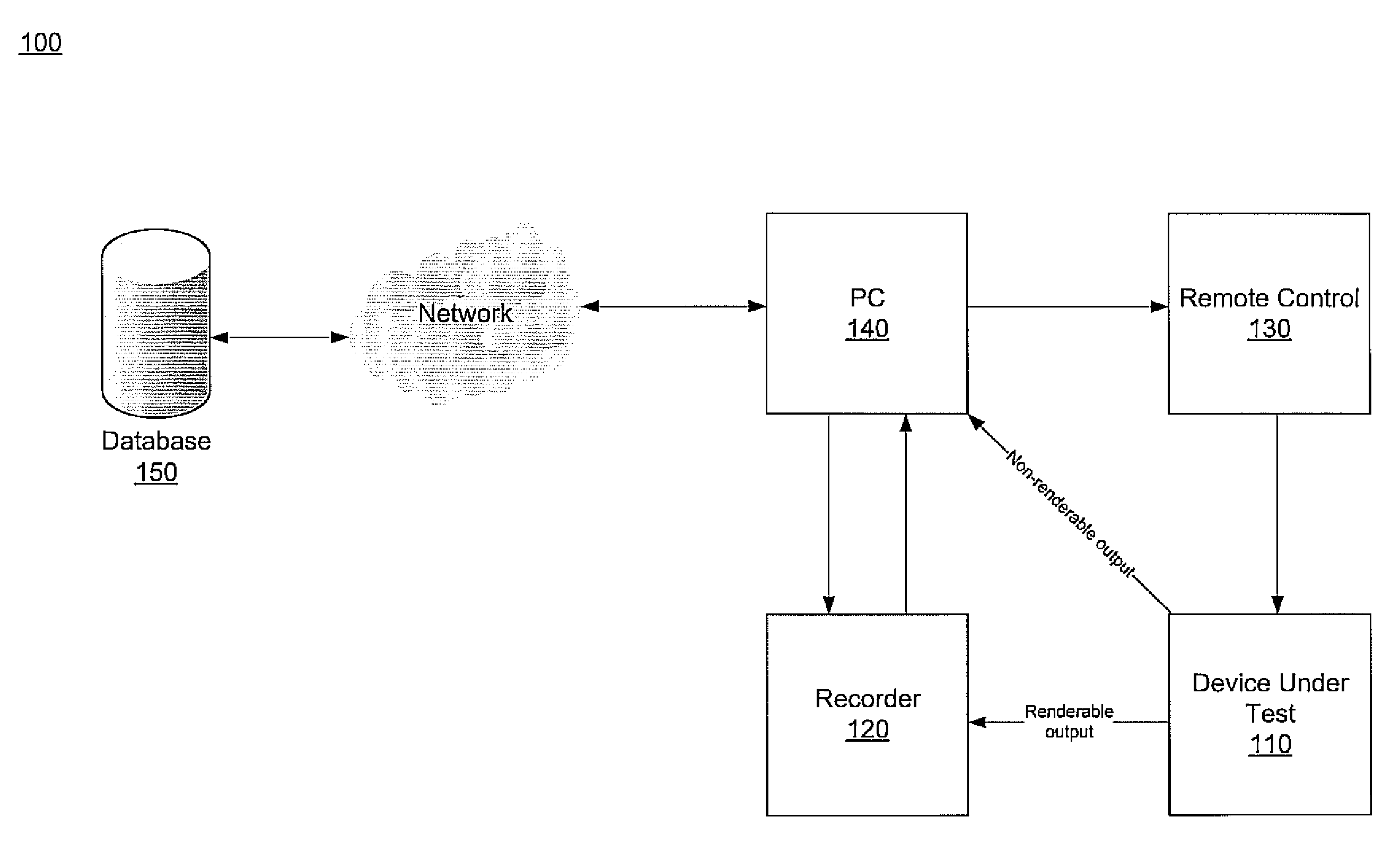
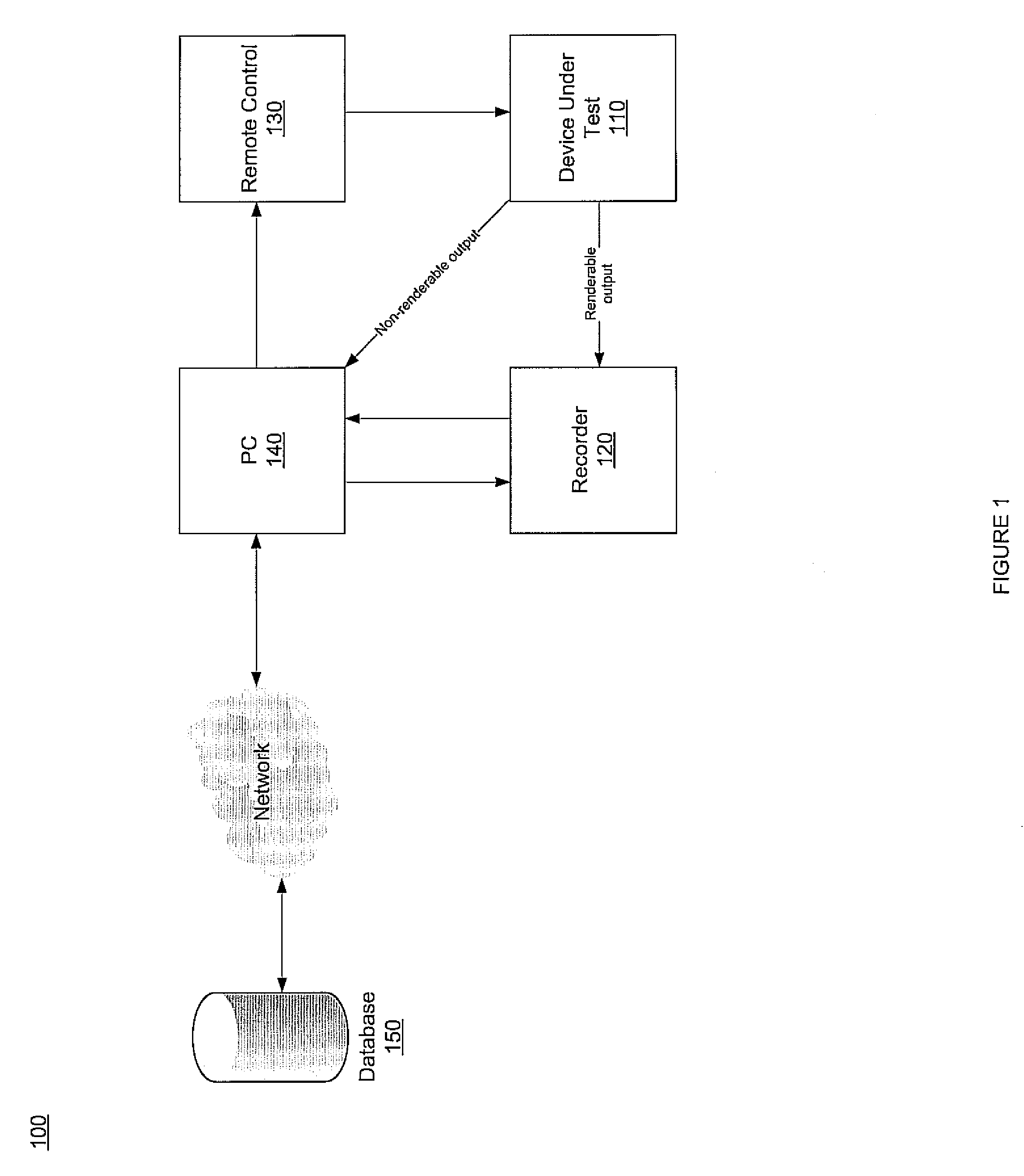
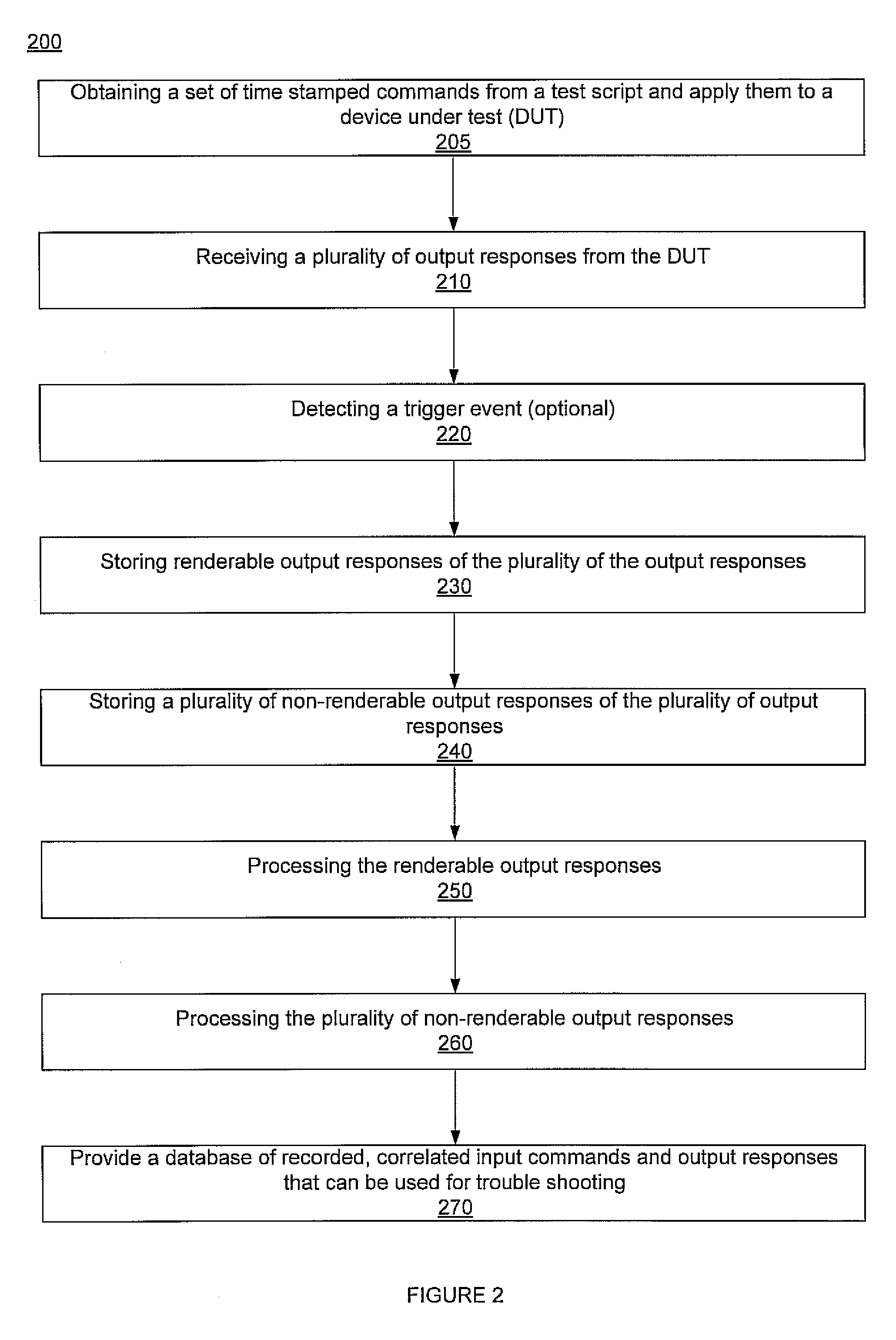
A computer controlled system of capturing and replaying test information. The system may comprise a device under test (DUT), e.g., a television set, a recording device, e.g., a camera, a memory component and a processor. The DUT receives test signals and responsive thereto generates a plurality of output responses. The recording device captures renderable output responses, e.g., image, audio, etc., of the plurality of output responses. The memory component stores the plurality of output responses. Non-renderable output responses are captured and stored in memory. Storing the responses may be responsive to a triggering event, e.g., detection of a new device. The processor may analyze data by correlating testing signals, renderable output responses and non-renderable output responses. The plurality of testing signals may be provided from a pre-programmed test script via a remote control. The plurality of testing signals and the plurality of output responses may be time coded and tagged.

Description

TECHNICAL FIELD[0001]Embodiments of the present invention relate to the field of electronics. More particularly, embodiments of the present invention relate to automatic testing of electronic devices.BACKGROUND ART[0002]In general, electronic devices are tested for integrity and functionality prior to customer release. For example, various functionalities of an electronic device may be thoroughly and independently tested to ensure integrity prior to its release to consumers.[0003]Television sets have become common items in most households. Various technologies may be used to manufacture television sets, e.g., plasma technology, liquid crystal display technology (LCD), light emitting diode (LED) technology, projection television technology, etc. Similar to other electronic devices, television sets are tested prior to their use by consumers.[0004]Testers employ various methods to capture the result of a given test in order to enable developers to duplicate the test result in an effort...

Claims


Application Information

Patent Timeline
IPC IPC(8): G06F17/40
CPCG06F11/2268
Inventor WU, MAX
Owner SONY CORP
Why Eureka
Try Eureka