Rotational blue light beam deer fly eliminator

a technology of blue light beam and deer fly, which is applied in the field of outdoor insect elimination, can solve the problems of destroying outdoor gatherings, difficult to eliminate, and overrun of bugs and flies, and achieves the effect of effectively eliminating deer flies

Inactive Publication Date: 2010-03-11
SCHOLZ RAYMOND
View PDF33 Cites 15 Cited by
  • Summary
  • Abstract
  • Description
  • Claims
  • Application Information

AI Technical Summary

Benefits of technology

[0011]In brief, the present invention will effectively eliminate deer flies from any area in which this item is used. A motor-driven tubular hollow cylindrical mask component surrounds a central vertical blue light and rotates around the blue light. The hollow cylindrical mask blacks out approximately 225-degrees around the blue light leaving a rotating vertical beam of blue light shining out through a vertical mask opening approximately 135 degrees wide. In this manner, the rotating vertical beam of blue light, similar to a lighthouse beacon, attracts deer flies that are normally not attracted to a brightly shining and fully visible blue light. These types of flies will enter through the surrounding exterior electrified screen to be electrically zapped and exterminated. The motor is positioned on the bottom of the unit and is powered by electricity. The motor-driven component can be made of any durable and weatherproof black material suitable for use near this type of light. The present invention preferably measures approximately 24″ high, 8″ long, and 8″ wide and is ready to hang in any outdoor location.
[0012]The present invention is a uniquely structured, outdoor, bug zapping product that will eradicate the deer flies and bell hornets that are not otherwise attracted to a standard bug-zapping unit. The present device offers an improved method for ridding an outdoor area of deer flies and bell hornets as it features a rotating component that will catch the eye of these insects. Attracted to movement, the flies and hornets will venture toward the periodically appearing light expecting a meal, only to be “zapped” on contact with the outer electrified screen. The painful bites of these annoying flies will no longer be felt with the addition of the present invention to any outdoor porch or patio area.

Problems solved by technology

For some, bugs and flies can overrun this relaxing family time or impromptu social event.
These flies are resistant to various forms of bug sprays as well, making them difficult to eliminate.
Without an adequate form of protection against such vicious flies, outdoor gatherings can be ruined.
Prior art devices fail to address the unique problems in eliminating these types of pests.

Method used


Image

  • Rotational blue light beam deer fly eliminator
  • Rotational blue light beam deer fly eliminator
  • Rotational blue light beam deer fly eliminator

Examples


Embodiment Construction

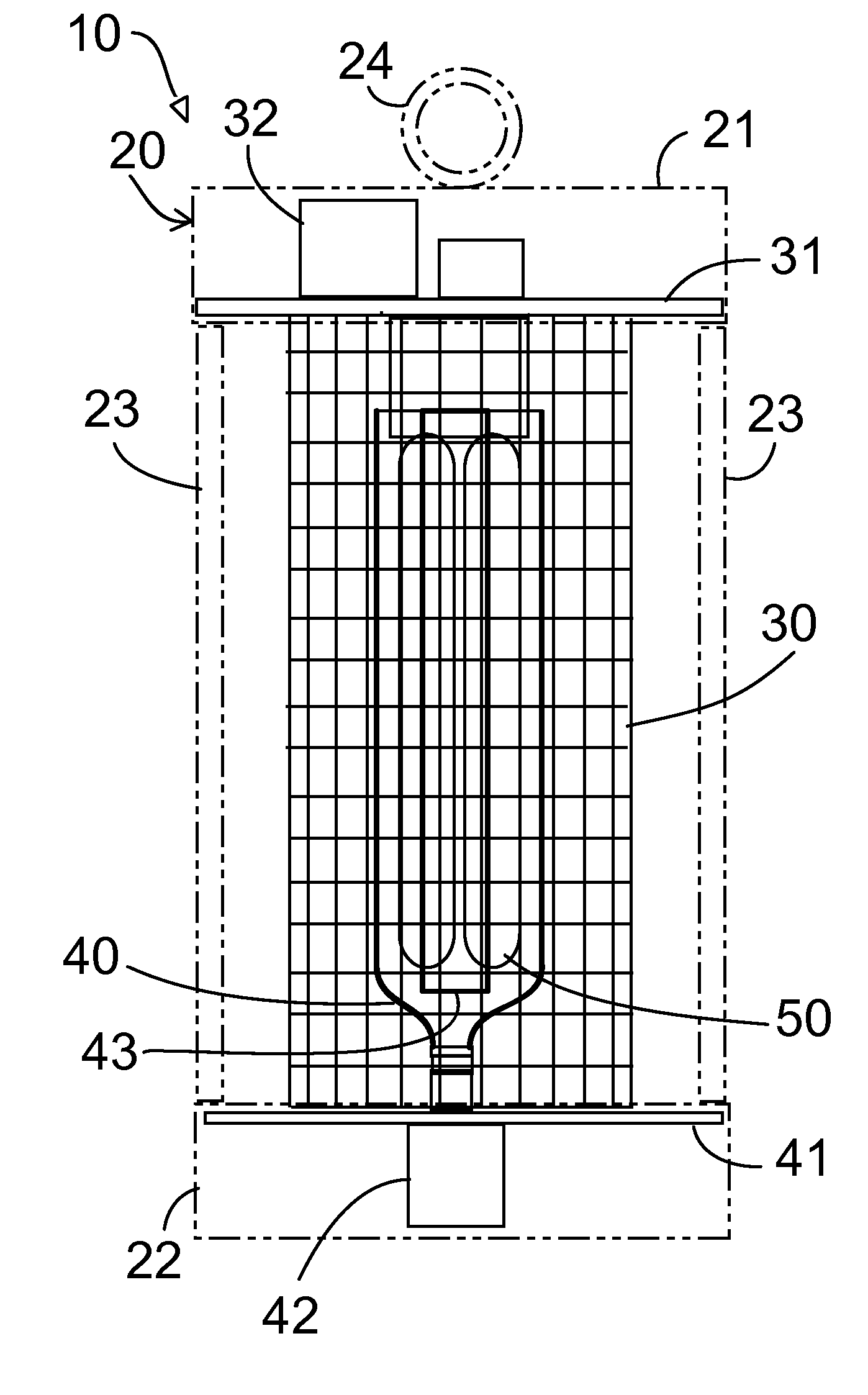
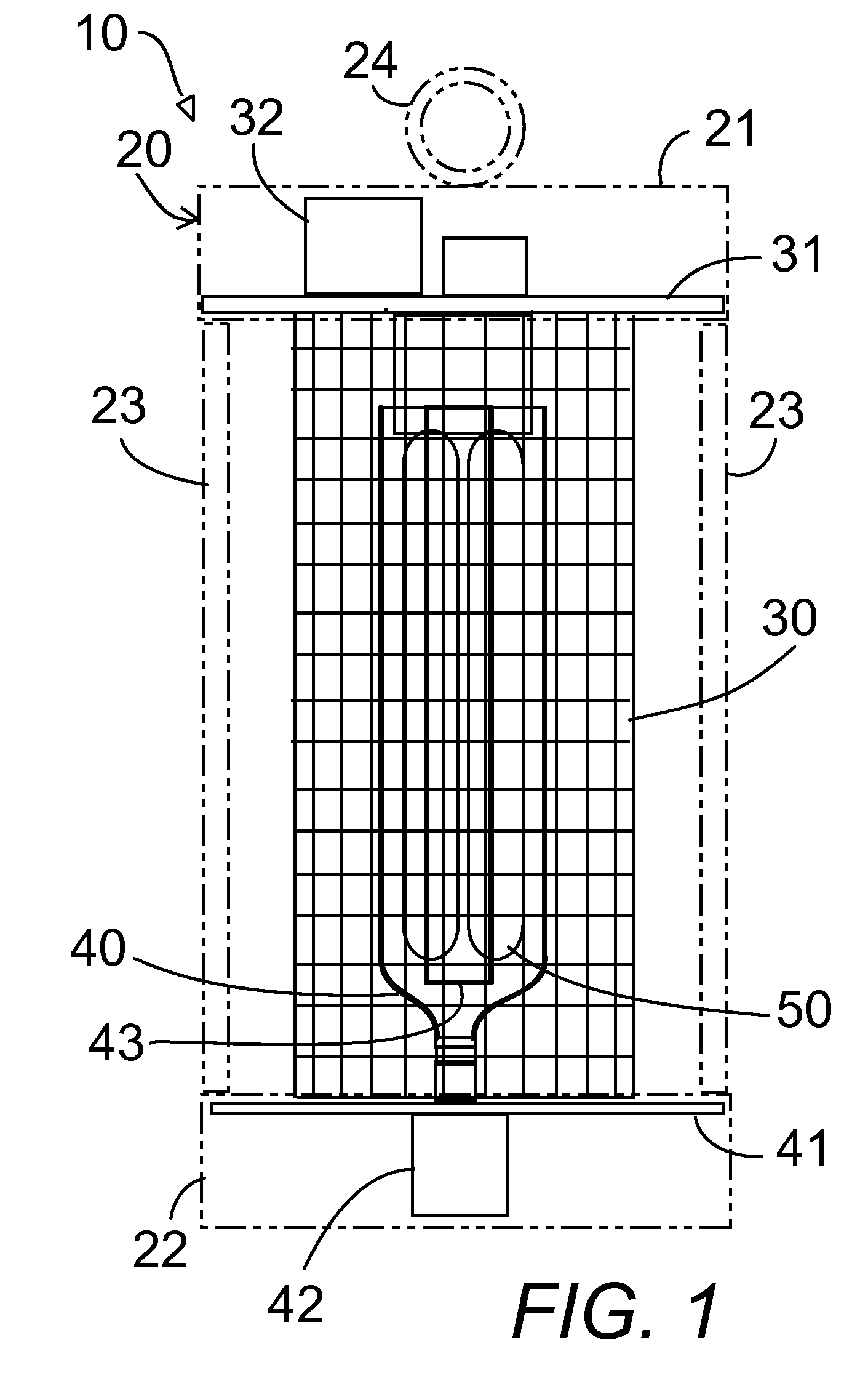
[0018]In FIGS. 1-4, an outdoor flying insect trap device 10 for attracting and exterminating flying insects comprises a vertical central blue light 50 surrounded by a motor-driven vertical rotating hollow cylindrical partial mask 40 emitting a rotating beam of blue light from inside an electrified wire insect exterminating cage 30. The rotating beam of blue light attracts flying insects which are exterminated by the exterminating cage 30.

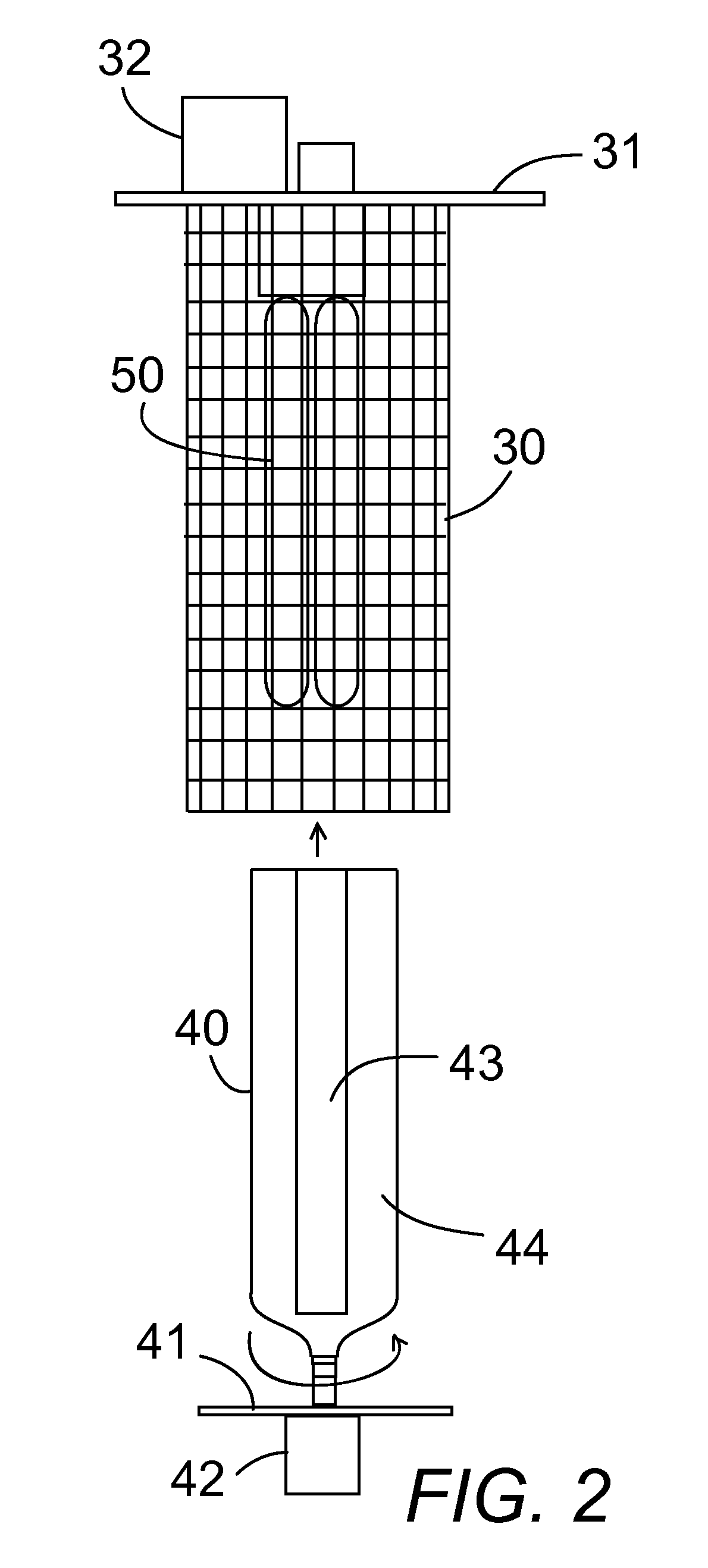
[0019]In FIG. 2, the blue light 50 hangs down from an upper plate 31 in a top housing 21 which is part of the outer support structure 20. The upper plate also supports the insect exterminating cage 30 hanging down from the upper plate 31. The cage 30 is electrified by a grid transformer 32 mounted on the upper plate 31.

[0020]The rotating partial mask 40 extends upwardly from a bottom plate 41 in a lower housing 22 which is part of the outer support structure 20. An electric motor 42 in the lower housing 22 turns the partial mask 40 in a circular mot...


PUM


Abstract

A motor-driven tubular hollow cylindrical partial mask component surrounds a central vertical blue light and rotates around the blue light. The hollow cylindrical partial mask blacks out a major portion of the blue light. A single vertical transparent slit in the partial mask admits blue light out to form a 360 degree scanning vertical beam of blue light as the partial mask rotates to attract deer flies, bell hornets and other flying insects. The flying insects enter through a surrounding exterior electrified cage to be electrically zapped and exterminated.

Description

CROSS-REFERENCE TO RELATED APPLICATIONS[0001]The present utility patent application claims the benefit of provisional application No. 60 / 954,461 filed Aug. 7, 2007.STATEMENT REGARDING FEDERALLY SPONSORED RESEARCH OR DEVELOPMENT[0002]Not Applicable.THE NAMES OF THE PARTIES TO A JOINT RESEARCH OR DEVELOPMENT[0003]Not Applicable.BACKGROUND OF THE INVENTION[0004]1. Field of the Invention[0005]The present invention relates to outdoor insect eliminators and in particular to a blue light with a rotating partial mask constantly rotating around the blue light to produce a rotating beam of blue light from inside of an electrified cage to attract and kill deer flies, bell hornets and other insects drawn to the rotating beam of blue light bug zapper, but not attracted to the traditional stationary bright light.[0006]2. Description of Related Art including information disclosed under 37 CFR 1.97 and 1.98[0007]Many outdoor-loving consumers enjoy spending time on a patio or open porch. For some, b...

Claims


Application Information

Patent Timeline
Patent Type & Authority Applications(United States)
IPC IPC(8): A01M1/22A01M1/04
CPCA01M1/223A01M1/04
Inventor SCHOLZ, RAYMOND
Owner SCHOLZ RAYMOND
Why Eureka
Try Eureka