

Centering Unit for Aligning at Least Two Grouped Vessels and Method for Aligning Two Grouped Vessels
a technology for grouped vessels and centering units, which is applied in the direction of packaging, transportation and packaging, packaging, etc., can solve the problems of difficulty in axial fixing of grouped vessels and lack of flexibility in the labelling of more than two grouped vessels
- Summary
- Abstract
- Description
- Claims
- Application Information
AI Technical Summary
Benefits of technology
Problems solved by technology
Method used
Image

Examples
first embodiment
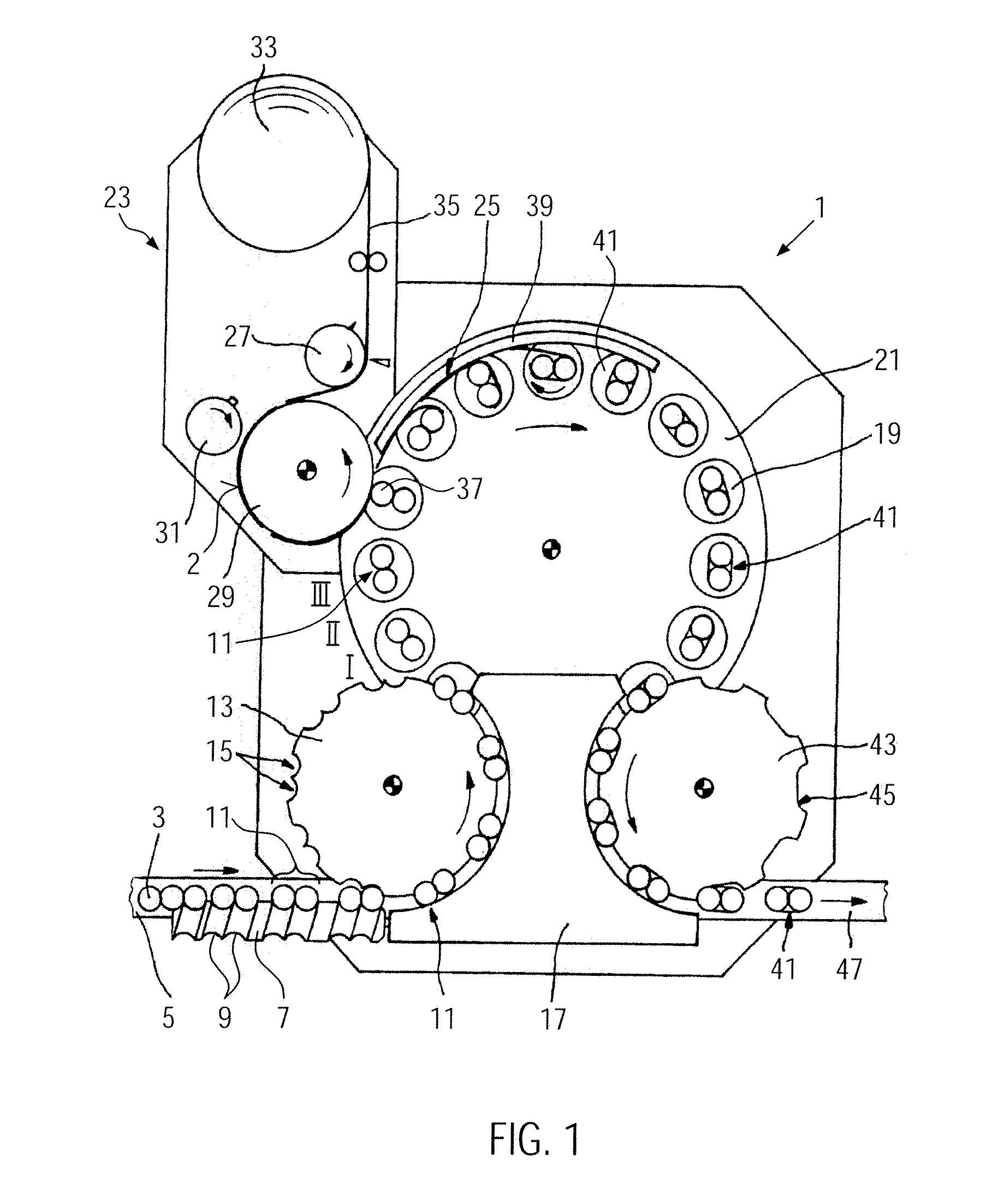
[0029]FIG. 1 shows a machine for treating at least two grouped vessels according to the present disclosure. The machine shown is a labelling machine 1. Vessels 3, in particular bottles or the like, are supplied to the machine 1 via a conveyor belt 5. In the present embodiment, the vessels are grouped in pairs 11 via an infeed worm in 7—thanks to the pitch of the screw flights 9 which increases in the conveying direction—and adjusted to the pitch of the infeed star wheel 13, which follows the infeed worm 7 and which is driven synchronously therewith. The infeed star wheel 13 has circumferentially distributed reception pockets 15 to which the bottle pairs 11 are transferred. A guide arc 17 allows, together with the infeed star wheel 13, a transfer of the bottle pairs 11 to rotary plates 19 of a treatment station 21.
[0030]The treatment station 21, which is here provided in the form of a carousel, comprises a plurality of regularly spaced rotary plates 19 of this type. The rotary plates...
second embodiment
[0044]FIG. 3 schematically shows, on the basis of three cross-sectional views, a second embodiment, viz. a method for aligning at least two grouped vessels according to the disclosure. Elements and features with reference numerals that have already been used in FIGS. 1 and 2 will not be described in detail once more. Reference is herewith made to the description of these elements and features.
[0045]The three states I to III shown in FIG. 3 occur at the points shown in FIG. 1 and located between the infeed star wheel 13 and the labelling module 23 in the labelling machine 1. The three states are schematically indicated by the Roman numerals I, II, III adjacent the carousel 21.
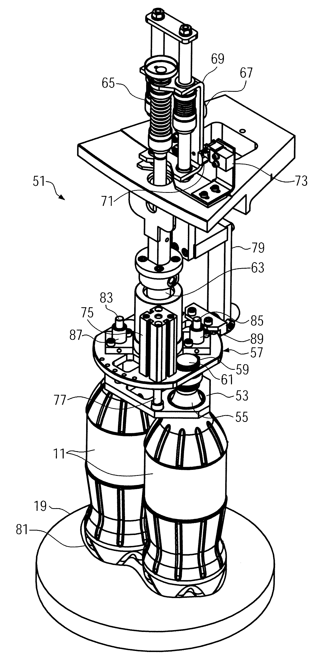
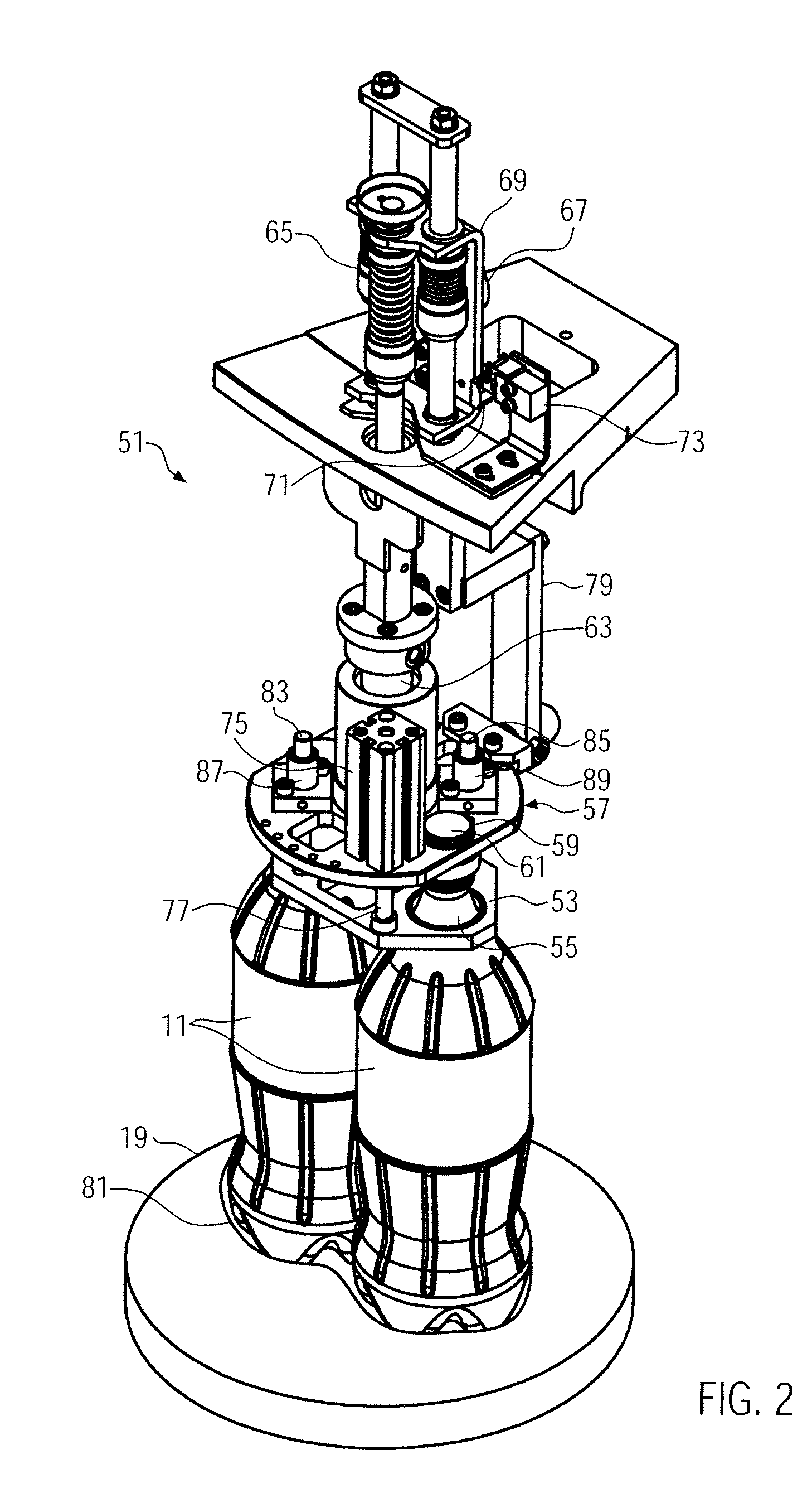
[0046]State I: When the infeed star wheel 13 has transferred a bottle pair 11 to a rotary plate 19, a centering unit 51 according to the first embodiment f the present disclosure is positioned slightly above the upper extremities 91 of the vessels 11. In this side view, the rotary connection 63, the two lift cyl...
third embodiment
[0060]FIG. 5 shows schematically a part of a centering unit 151 for centering grouped vessels according to the present disclosure. The figure shows a detail of a centering unit which can be used in the machine shown in FIG. 4. Features with reference numerals that have already been used in one of the FIGS. 1 to 4 will not be described in detail once more. Reference is herewith made to the description of these features.
[0061]In FIG. 5 only the lower part of a centering unit 151 is shown. The final centering means 153, which are here again a plate and which are provided with six vessel reception openings 155, 157, 159, 161, 163, 165, can be seen in this figure. Below the final centering means 153 three subcentering means are disposed, which are again defined by plates 167, 169 and 171 and which are arranged independently of one another. These plates 167, 169 and 171 define the precentering means 53. Each of these subcentering means 167, 169, 171 is provided with two vessel reception o...
PUM
 Abstract
Description
Claims
Application Information