Viscometer with integral sample retention reservoir

a technology of integral sample and reservoir, which is applied in the direction of direct flow property measurement, instruments, measurement devices, etc., can solve the problems of mechanized sample loading in automated viscometers, and the inability to retain the same fluid sample in the tube for repeat testing, so as to prevent the siphoning effect of sampl

Active Publication Date: 2010-03-11
CANNON INSTR
View PDF17 Cites 4 Cited by
  • Summary
  • Abstract
  • Description
  • Claims
  • Application Information

AI Technical Summary

Benefits of technology

[0004]In another embodiment, a viscometer is provided which includes a substantially horizontal reservoir comprising a trap at one end for retaining a sample in the reservoir. The trap has a low point for retaining a predetermined sample volume in the reservoir. A substantially vertical measuring tube extends substantially upwardly from the reservoir and is disposed substantially perpendicularly thereto. The measuring tube includes a timing bulb, an upper timing sensor disposed above the timing bulb, a lower timing sensor disposed below the timing bulb, and a capillary tube located below the lower timing sensor. The capillary tube connects to the reservoir at an opposite end from the trap. A junction interconnects the trap, a generally downwardly projecting fill tube, and a generally upwardly projecting vent tube. The junction has a peak located at least slightly vertically above the trap low point to prevent siphoning of the sample.

Problems solved by technology

In a U-shaped viscometer such as a Ubbelohde or Ostwald-style, a fluid sample must typically be added to the second branch tube and held in the reservoir, which presents difficulties for mechanized sample loading in automated viscometers.
Because an Atlantic tube does not contain a reservoir, the same fluid sample cannot be retained in the tube for repeat testing to improve accuracy or for extended periods of thermal soaking prior to testing.

Method used


Image

  • Viscometer with integral sample retention reservoir
  • Viscometer with integral sample retention reservoir
  • Viscometer with integral sample retention reservoir

Examples


Embodiment Construction

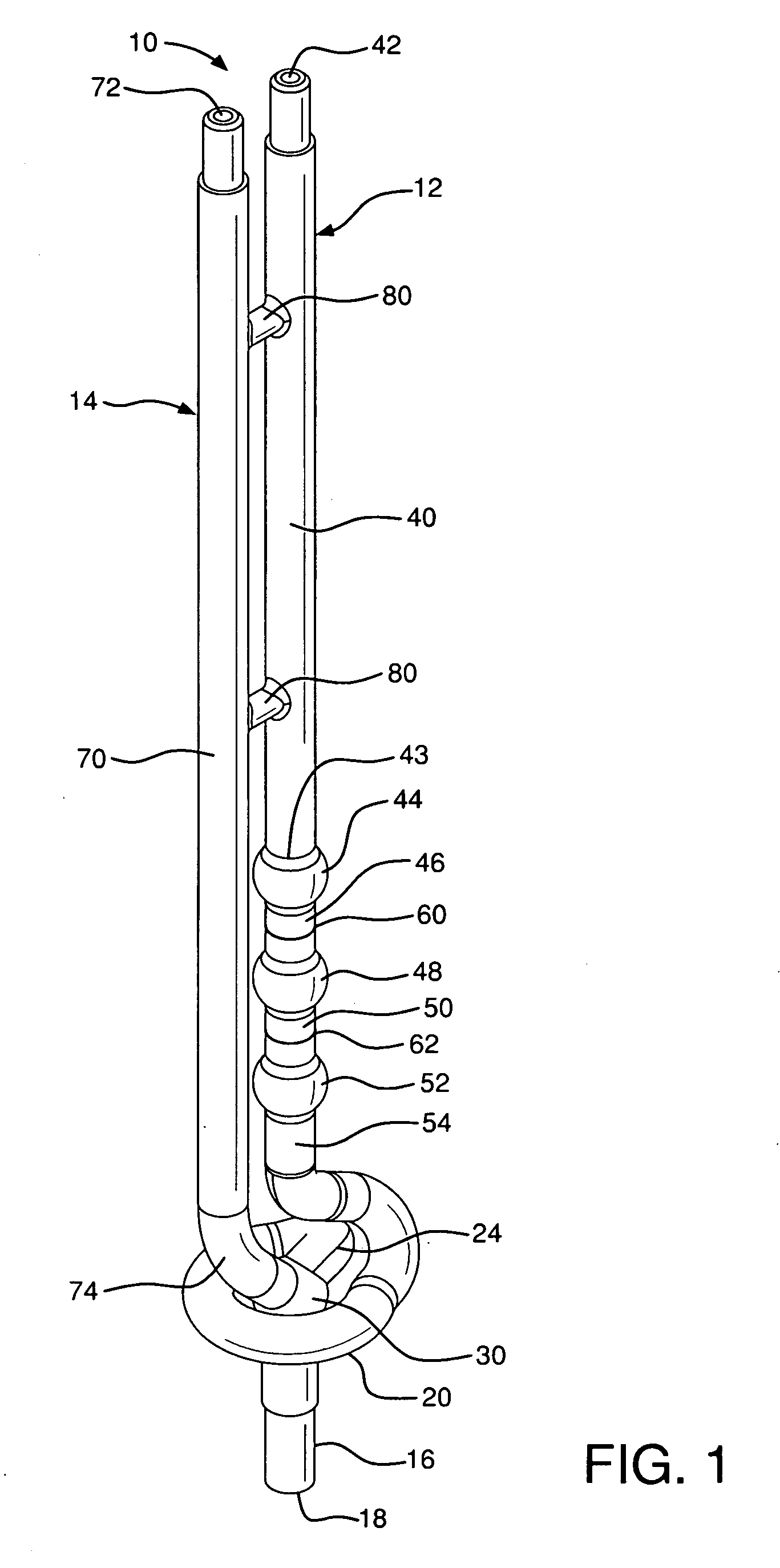
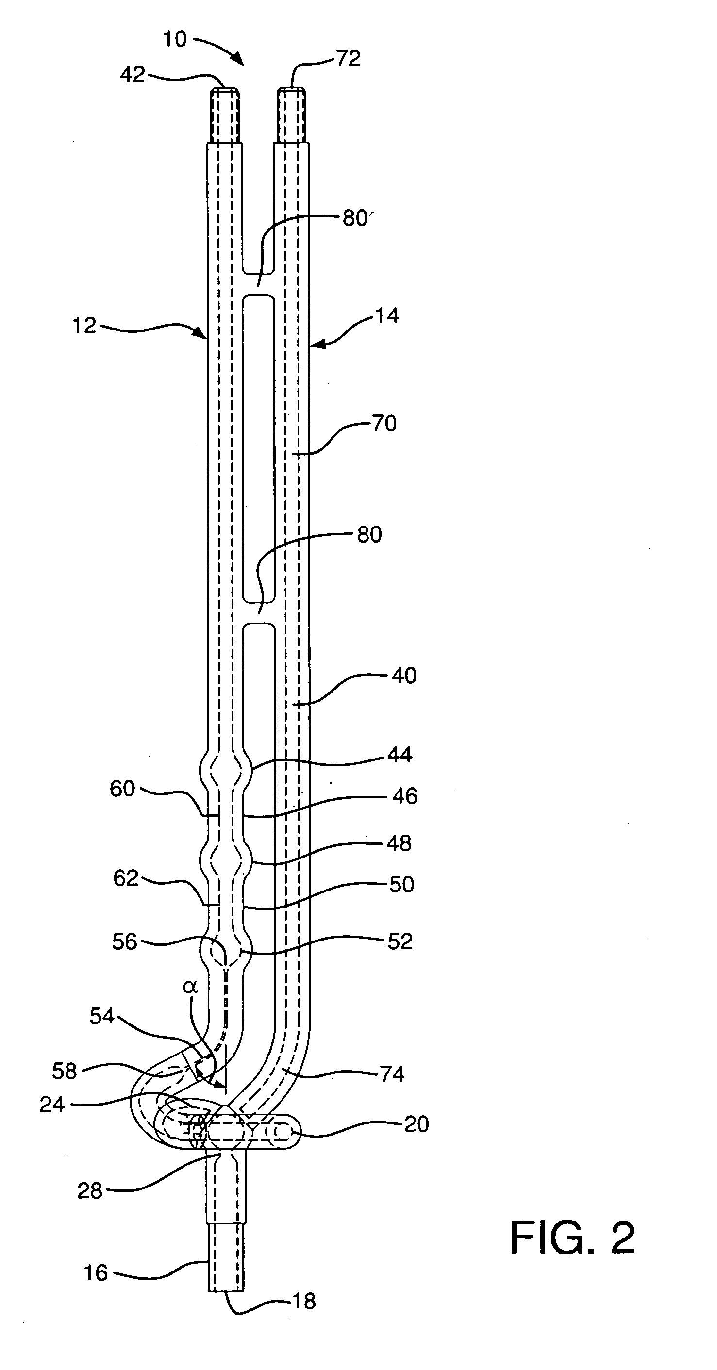
[0013]There is shown in FIGS. 1 and 2 a viscometer 10 comprising a vent tube 14, a fill tube 16, and a measuring tube 12 comprising a reservoir 20. The reservoir 20, the vent tube 14, and the fill tube 16 are interconnected together at a junction 30 so that fluid can pass therebetween. As depicted in the embodiment of FIGS. 1 and 2, the reservoir 20 depends outwardly from the junction 30 in a substantially horizontal orientation and is preferably wrapped generally around a portion of one or both of the junction 30 and the fill tube 16 so as to form a partial ring or helical shape. As depicted in the embodiment of FIG. 6, the reservoir 20 extends outwardly in a substantially straight horizontal orientation and is disposed generally in the same plane as the measuring tube 12, the vent tube 14, and the fill tube 16. In either embodiment, the reservoir 20 is preferably substantially perpendicular to the measuring tube 12. The viscometer 10 can be made of borosilicate glass. Alternativel...


PUM

PropertyMeasurementUnit
angleaaaaaaaaaa
angleaaaaaaaaaa
angleaaaaaaaaaa

Abstract

A viscometer having a substantially horizontal reservoir including a trap for retaining a sample indefinitely in the reservoir. A substantially vertical measuring tube disposed perpendicularly to the substantially horizontal reservoir and depends substantially upwardly from the reservoir. A junction interconnects the trap, a generally downwardly projecting fill tube, and a generally upwardly projecting vent tube.

Description

BACKGROUND OF INVENTION [0001]Glass capillary viscometers of many sizes and configurations are known in the art, including three basic types—suspended level, reverse flow, and Ostwald-style. Perhaps the most commonly used viscometers are the Ubbelohde viscometer (suspended level) and the Cannon-Fenske Routine (Ostwald-style) viscometer. Such viscometers typically comprise a generally U-shaped tube having a first branch tube with a capillary tube of a precise narrow diameter and a second branch tube having a reservoir or bulb for holding a sample of a fluid whose viscosity is to be measured. The tops of the U-shape of these viscometers permit the devices to be immersed and maintained in a closed-bottom bath of liquid which is thermostatically controlled, while allowing the sample to be manipulated under pressure or vacuum or allowed to free-flow under the influence of gravity in the viscometer. The reservoir enables a sample to be held for repeat testing and allows for accurate tempe...

Claims


Application Information

Patent Timeline
Patent Type & Authority Applications(United States)
IPC IPC(8): G01N11/06
CPCG01N11/06
Inventor MAGGI, CHARLES PATRICKPOILLUCCI, BRIAN JAMESCARR, KEITH GRAHAMCARBALAN, FRANK L.
Owner CANNON INSTR
Why Eureka
Try Eureka