Engine start system for use in idle stop system for automotive vehicle

a technology for automotive vehicles and start systems, which is applied to engine starters, combustion engines, electric motor starters, etc., can solve problems such as vehicle operators' discomfort, engine restart control encounters problems, and vehicle operators' discomfort, and achieve the effect of reducing fuel consumption

Active Publication Date: 2010-03-11
DENSO CORP
View PDF20 Cites 91 Cited by
  • Summary
  • Abstract
  • Description
  • Claims
  • Application Information

AI Technical Summary

Benefits of technology

[0018]It is therefore an object of the invention to provide a simplified structure of an engine start system which may be employed in automotive vehicles and is

Problems solved by technology

Such engine restart control encounters a problem especially when the engine restart request is made after the engine stop request is made, but before the engine stops completely.
Specifically, in such an event, restarting of the engine after it stops completely may lead to concern about the discomfort of the vehicle operator.
However, when the accelerator pedal is depressed by the vehicle operator immediately after the engine is requested to stop, the engine may fail to restart quickly, thus causing the vehicle operator to feel uncomfortable.
The above system, however, poses the problem that the engagement of the pinion gear with the ring gear achieved each time the engine restart request is made generates mechanical noise with which vehicle occupants usually feel uncomfortable.
This, however, requires a current control circuit such as a chopper circuit, thus resulting in a complex structure of the system.
The system, as taught in either of the above publications, is designed to supply the electric power to the starter motor when the engine restart request is not made, thus resulting in an increase in consumption of power in the battery.
This leads to a great concern about an increase in consumption of fuel in the automotive vehicle or a lack of electric power to be supplied to electric acce

Method used


Image

  • Engine start system for use in idle stop system for automotive vehicle
  • Engine start system for use in idle stop system for automotive vehicle
  • Engine start system for use in idle stop system for automotive vehicle

Examples


Embodiment Construction

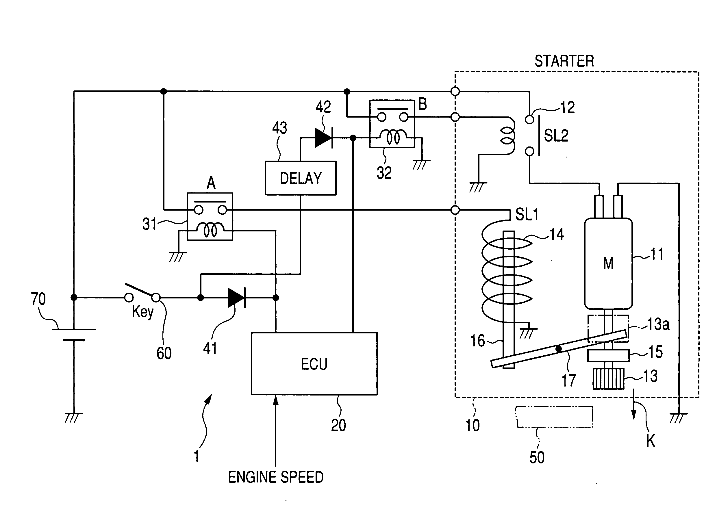
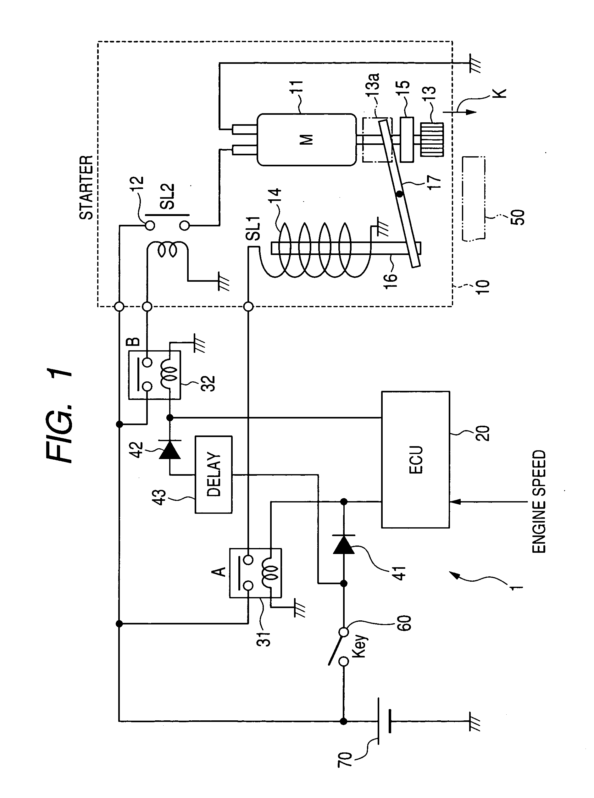
[0074]Referring to the drawings, wherein like reference numbers refer to like parts in several views, particularly to FIG. 1, there is shown an engine start system 1 according to the first embodiment of the invention which is used with an idle stop system to stop an automotive engine automatically when a vehicle has stopped, for example, at an intersection.

[0075]The engine start system 1 includes a starter 10, an electronic control unit (ECU) 20, two drive relays 31 and 32, and two diodes 41 and 42.

[0076]The starter 10 is equipped with a starter motor 11, a relay switch 12 to supply electric power to the starter motor 11, a pinion gear 13, and a solenoid 14 working as an actuator to move the pinion gear 13 between an engaged position and a disengaged position, which will be described later in detail.

[0077]The starter motor 11 is connected at one of ends thereof to a storage battery 70 through the relay switch 12 and at the other end to ground. When the relay switch 12 is turned on, ...


PUM


Abstract

An engine start system which may be employed in automotive idle stop systems. The engine start system includes a pinion gear to be pushed to a ring gear coupled to an engine for achieving meshing engagement with the ring gear. After the pinion gear engages the ring gear, the engine start system starts to rotate the pinion gear using a starter motor to crank the engine. Specifically, when an engine restart request is made following an engine stop request, the engine start system waits until after the speed of the engine drops below a preselected gear engageble speed and then moves the pinion gear toward the ring gear without rotating the pinion gear. This minimizes the consumption of fuel in the vehicle in supplying electric power to the starter motor and a maximum level of mechanical noise arising from the engagement of the pinion gear with the ring gear.

Description

CROSS REFERENCE TO RELATED DOCUMENT[0001]The present application claims the benefits of Japanese Patent Application Nos. 2008-229885 filed on Sep. 8, 2008 and 2009-45433 filed on Feb. 27, 2009, disclosures of which are incorporated herein by reference.BACKGROUND OF THE INVENTION[0002]1. Technical Field of the Invention[0003]The present invention relates generally to an engine start system for use in an idle stop system for automotive vehicles (also called an automatic engine stop / restart system) which works to stop an automotive engine automatically, for example, when the vehicle has stopped at an intersection or due to a traffic jam and then restart the engine when the vehicle driver performs a given starting operation (e.g., upon release of the driver's foot from the brake pedal).[0004]2. Background Art[0005]There are known automotive idle stop systems designed to stop the engine automatically when an output of the engine is required not to be produced and restart the engine autom...

Claims


Application Information

Patent Timeline
IPC IPC(8): F02N11/00
CPCF02N11/0844Y02T10/48F02N15/067F02N11/0855Y02T10/40
Inventor SENDA, TAKASHIKATO, AKIRAOKUMOTO, KAZUSHIGEMURATA, MITSUHIRONIIMI, MASAMIHARUNO, KIYOKAZU
Owner DENSO CORP
Why Eureka
Try Eureka