Method for operating a lean burn engine with an aftertreatment system including nonthermal plasma discharge device

a lean burn engine and aftertreatment technology, which is applied in the direction of engines, machines/engines, mechanical apparatus, etc., can solve the problems of reducing nox at high efficiency, reducing nox conversion efficiency, and few lean burn gasoline engines in production, so as to minimize overall fuel consumption

Inactive Publication Date: 2005-09-22
FORD GLOBAL TECH LLC
View PDF15 Cites 2 Cited by
  • Summary
  • Abstract
  • Description
  • Claims
  • Application Information

AI Technical Summary

Benefits of technology

[0011] An advantage of the present invention is that the conversion of NO to NO2 is performed without consuming more fuel than necessary. That is, the amount of fuel supplied and the electrical energy are adjusted to provide the desired conversion rate while minimizing overall fuel consumption.
[0012] A further advantage of the present invention is a method for providing the desired conversion rate of NO to NO2.
[0013] Other advantages, as well as objects and features of the present invention, will become apparent from the following detailed description of the preferred embodiments when taken in connection with the accompanying drawings.

Problems solved by technology

Presently, there are very few lean burn gasoline engines in production due to difficulties in meeting emission requirements.
The difficulty is that conventional precious metal catalyst oxidizes CO and hydrocarbons and reduces NOx at high efficiency when the air-fuel mixture is very close to stoichiometric; but, NOx conversion efficiency drops off substantially when the exhaust gases are lean.
A known problem with lean NOx traps is their susceptibility to SOx contamination.
These become absorbed in the LNT and reduce its conversion efficiency.
The inventors of the present invention have recognized several problems with sulfur contamination: first, the LNT operates at less than its optimal efficiency for much of the time due to the sulfur contamination and secondly, the deSOx operation is cumbersome, penalizes fuel economy, and the deSOx temperature is near the temperature at which permanent damage to the LNT occurs making control of deSOx regeneration a challenge.
Furthermore, deSOx regeneration is not completely reversible.
The propensity of an oxidation catalyst to oxidize SO2 to SO3 is harmful to the LNT.

Method used


Image

  • Method for operating a lean burn engine with an aftertreatment system including nonthermal plasma discharge device
  • Method for operating a lean burn engine with an aftertreatment system including nonthermal plasma discharge device
  • Method for operating a lean burn engine with an aftertreatment system including nonthermal plasma discharge device

Examples


Embodiment Construction

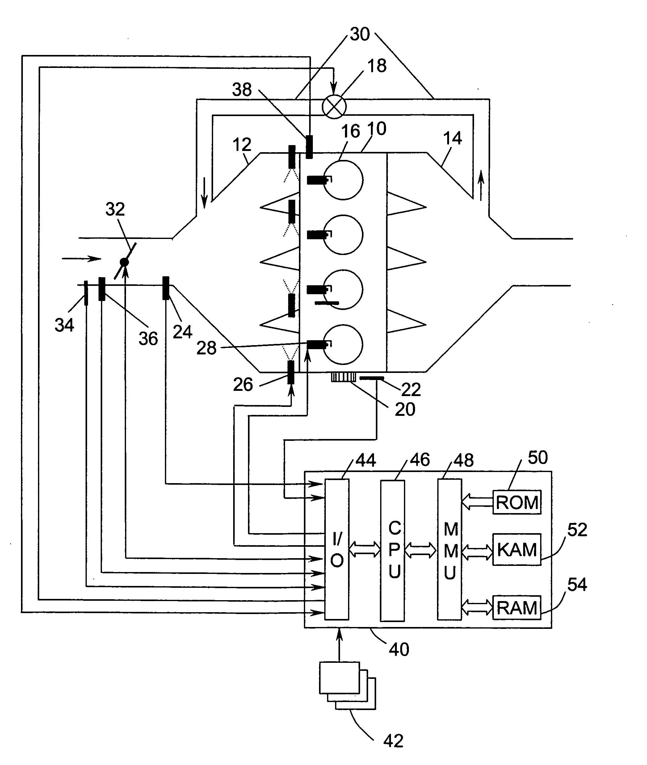
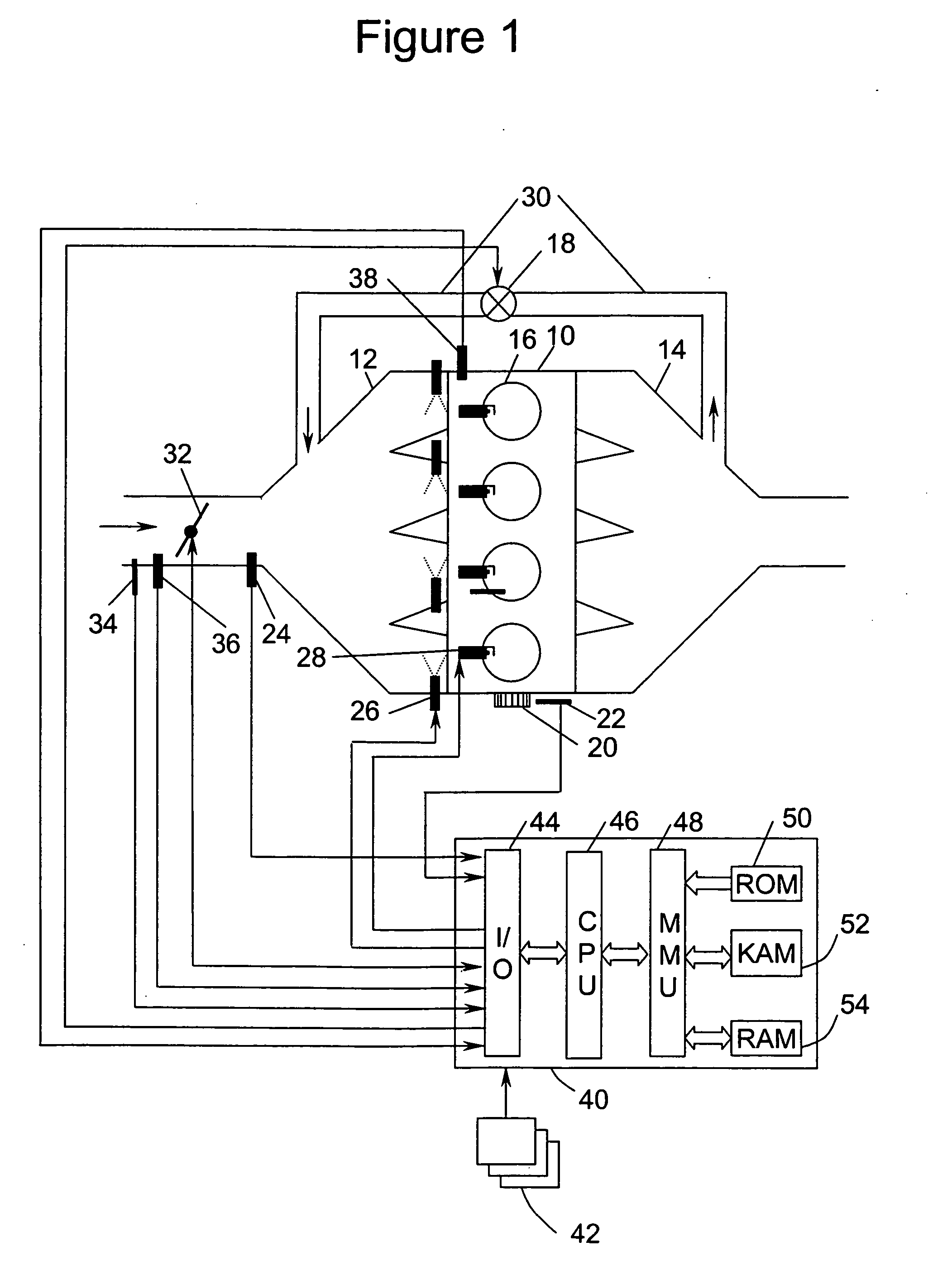
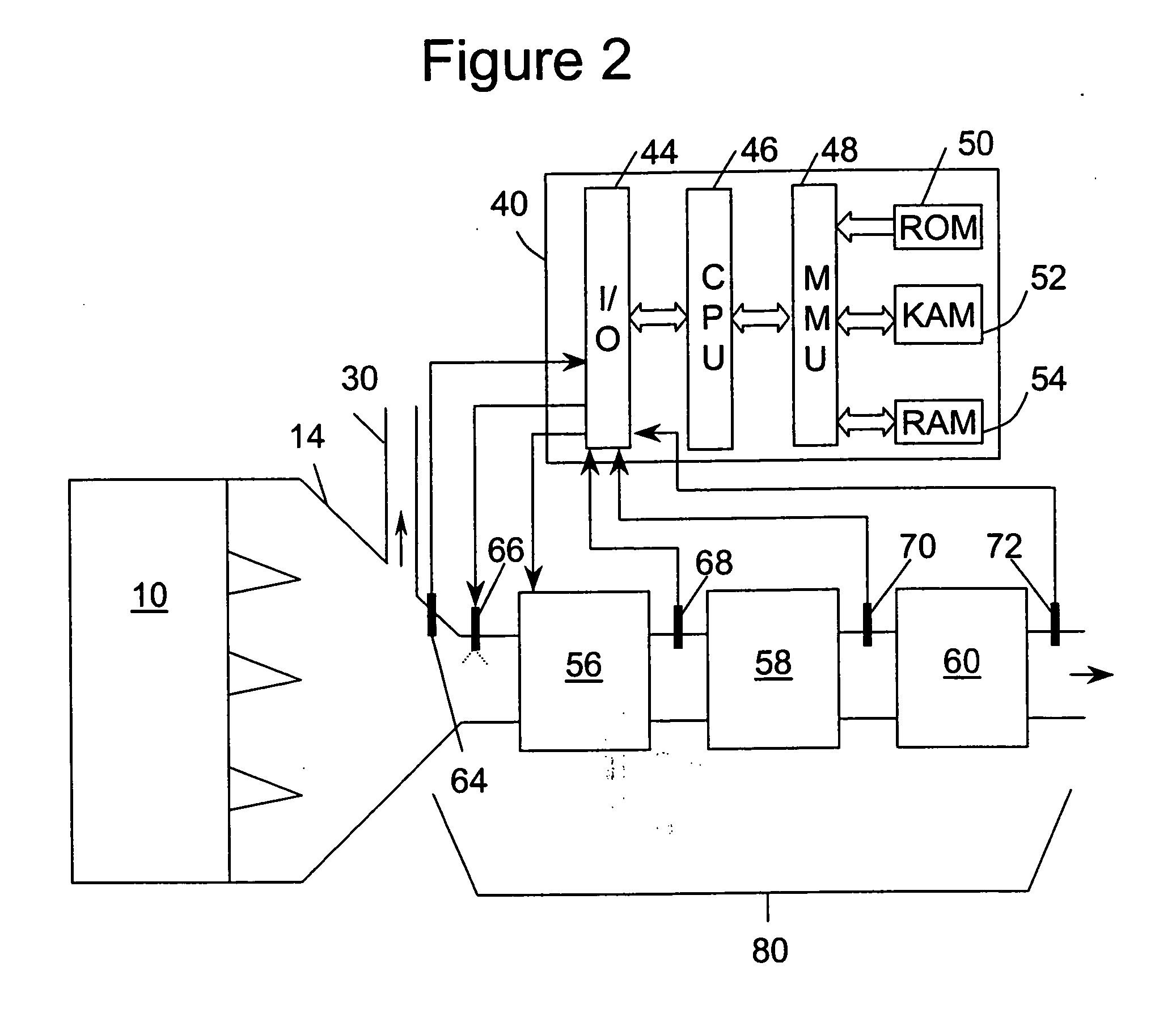
[0018] A 4-cylinder internal combustion engine 10 is shown, by way of example, in FIG. 1. Engine 10 is supplied air through intake manifold 12 and discharges exhaust gases through exhaust manifold 14. An intake duct upstream of the intake manifold 12 contains a throttle valve 32 which, when actuated, controls the amount of airflow to engine 10. Sensors 34 and 36 installed in intake manifold 12 measure air temperature and mass airflow (MAF), respectively. Sensor 24, located in intake manifold 14 downstream of throttle valve 32, is a manifold absolute pressure (MAP) sensor. A partially closed throttle valve 32 causes a pressure depression in intake manifold 12. When a pressure depression exists in intake manifold 12, exhaust gases are caused to flow through exhaust gas recirculation (EGR) duct 30, which connects exhaust manifold 14 to intake manifold 12. Within EGR duct 30 is EGR valve 18, which is actuated to control EGR flow. Fuel is supplied to engine 10 by fuel injectors 26. Each ...


PUM


Abstract

In an exhaust aftertreatment system, which includes a nonthermal plasma discharge device followed by a NOx storage device followed by a precious metal catalyst, a method is disclosed for operating the engine at a lean air-fuel ratio when the NOx storage device is not full and for operating the engine rich when the NOx storage device is substantially full. Electrical energy supplied to the nonthermal plasma discharge device during lean operation is discontinued during rich operation of the engine.

Description

FIELD OF INVENTION [0001] The present invention relates to an aftertreatment system for treating exhaust gases from a lean burn engine and, more particularly, to an aftertreatment system comprising a nonthermal plasma discharge device. BACKGROUND OF THE INVENTION [0002] It is well known by those skilled in the art that internal combustion engines burning a lean mixture of fuel and air consume significantly less fuel than when operating at a stoichiometric mixture of air and fuel. Presently, there are very few lean burn gasoline engines in production due to difficulties in meeting emission requirements. The difficulty is that conventional precious metal catalyst oxidizes CO and hydrocarbons and reduces NOx at high efficiency when the air-fuel mixture is very close to stoichiometric; but, NOx conversion efficiency drops off substantially when the exhaust gases are lean. [0003] It is known in the art to use a lean NOx trap (LNT) aftertreatment system for processing the products of lean...

Claims


Application Information

Patent Timeline
Patent Type & Authority Applications(United States)
IPC IPC(8): F01N3/00F01N3/08F01N3/10
CPCF01N3/0871Y02T10/20F01N2430/06F01N2240/28Y02T10/12
Inventor HOARD, JOHN W.SURNILLA, GOPICHANDRA
Owner FORD GLOBAL TECH LLC
Why Eureka
Try Eureka