Applied-ignition internal combustion engine with catalytically coated injection device, and method for operating an internal combustion engine of said type

a technology of catalytic coating and injection device, which is applied in the direction of combustion engines, fuel injection apparatus, charge feed systems, etc., can solve the problems of affecting the combustion efficiency of mixture preparation, affecting the efficiency of combustion, and small quantities of fuel which adhere to the injection device during the injection, so as to reduce pollutant emissions and reduce fuel consumption.

Active Publication Date: 2013-09-12
FORD GLOBAL TECH LLC
View PDF8 Cites 3 Cited by
  • Summary
  • Abstract
  • Description
  • Claims
  • Application Information

AI Technical Summary

Benefits of technology

[0003]In the development of internal combustion engines, it is constantly sought to minimize fuel consumption and reduce pollutant emissions.

Problems solved by technology

However, quantity regulation by a throttle flap has thermodynamic disadvantages in the partial load range owing to throttling losses.
In the case of the direct injection of fuel, problems are caused by the coking of the injection device, for example of an injection nozzle which is used for the injection.
Small quantities of fuel which adhere to the injection device during the injection may undergo incomplete combustion under oxygen-deficient conditions.
Said coking residues may firstly disadvantageously change the geometry of the injection device and influence or hinder the formation of the injection jet, and thereby sensitively disrupt mixture preparation.
Secondly, injected fuel accumulates in the porous coking residues, which fuel, often toward the end of the combustion when the oxygen provided for the combustion has been almost completely consumed, then undergoes incomplete combustion and forms soot, which in turn contributes to the increase in particle emissions.
Furthermore, coking residues may become detached for example as a result of mechanical loading caused by a pressure wave propagating in the combustion chamber or the action of the injection jet.
The residues detached in this way may lead to damage in the exhaust-gas discharge system, and for example impair the functional capability of exhaust-gas aftertreatment systems provided in the exhaust-gas discharge system.
Both measures may contribute to fuel consumption and pollutant emissions.
The injection of water is however not suitable in partial load operation at low loads and low rotational speeds, because this harbors the risk of corrosion in the combustion chamber and in the exhaust-gas discharge system, and may yield disadvantages in terms of wear.
A disadvantage of the method described in EP 1 404 955 B1 for the reduction of coking residues by oxidation is that, even when using catalytic materials, the minimum temperatures required for the oxidation may not be reached in partial load operation at low loads and low rotational speeds.
In this respect, the method of DE 101 17 519 A1 also does not permit the depletion of coking residues, that is to say cleaning by oxidation, at low loads and low rotational speeds of the internal combustion engine.
This is because the low temperature level expedites the formation of coking residues and also makes the removal of said residues more difficult.

Method used


Image

  • Applied-ignition internal combustion engine with catalytically coated injection device, and method for operating an internal combustion engine of said type
  • Applied-ignition internal combustion engine with catalytically coated injection device, and method for operating an internal combustion engine of said type
  • Applied-ignition internal combustion engine with catalytically coated injection device, and method for operating an internal combustion engine of said type

Examples


Embodiment Construction

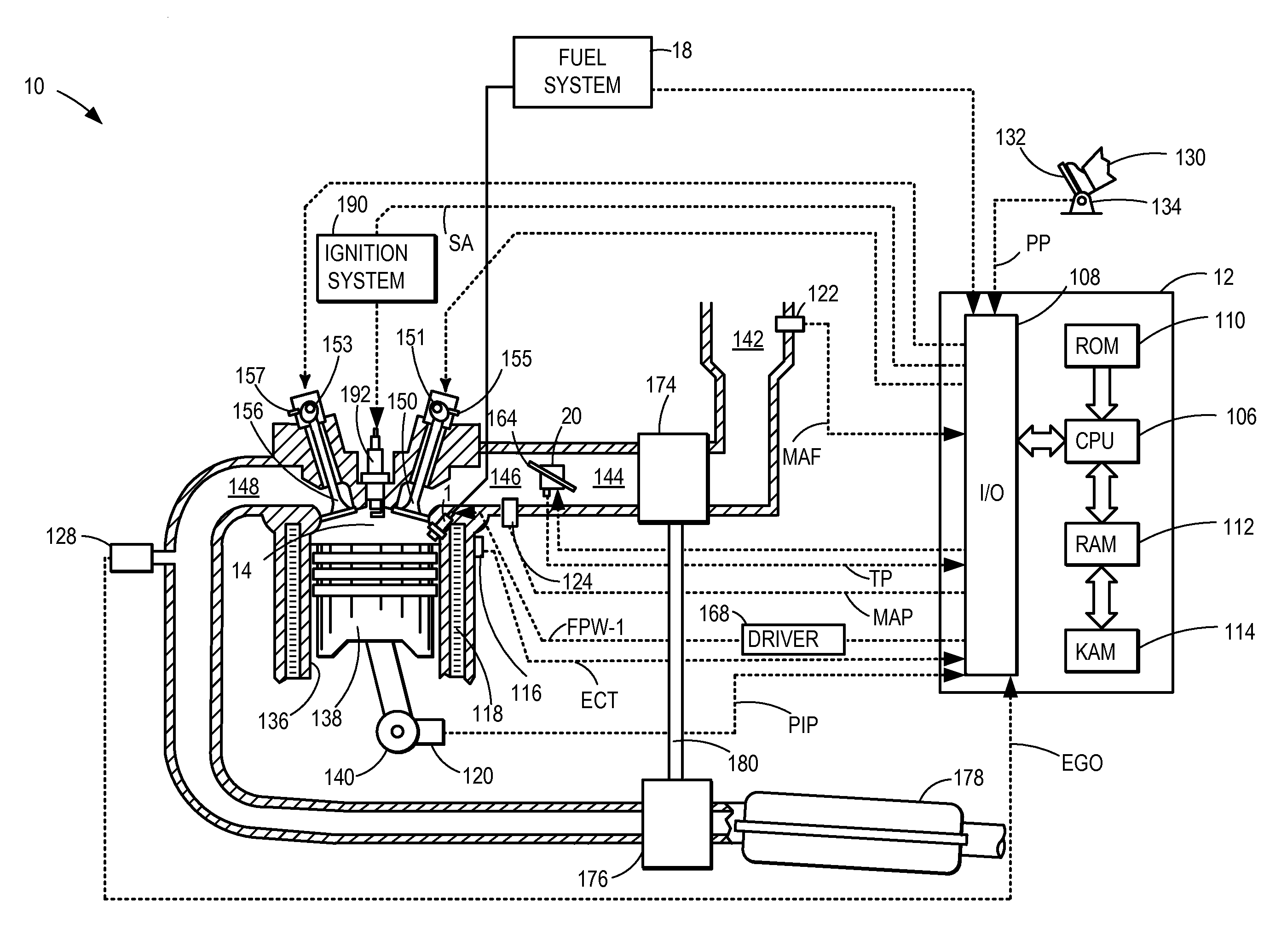
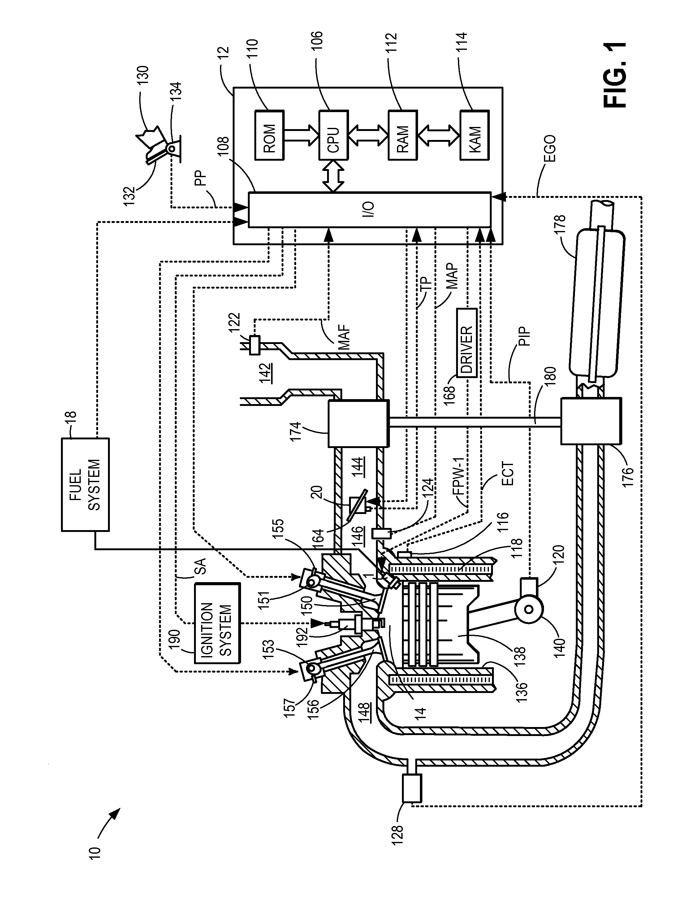
[0036]Referring now to the figures, FIG. 1 depicts an example embodiment of a combustion chamber or cylinder of internal combustion engine 10. Engine 10 may receive control parameters from a control system including controller 12 and input from a vehicle operator 130 via an input device 132. In this example, input device 132 includes an accelerator pedal and a pedal position sensor 134 for generating a proportional pedal position signal PP. Cylinder (herein also “combustion chamber’) 14 of engine 10 may include combustion chamber walls 136 with piston 138 positioned therein. Piston 138 may be coupled to crankshaft 140 so that reciprocating motion of the piston is translated into rotational motion of the crankshaft. Crankshaft 140 may be coupled to at least one drive wheel of the passenger vehicle via a transmission system. Further, a starter motor may be coupled to crankshaft 140 via a flywheel to enable a starting operation of engine 10.

[0037]Cylinder 14 can receive intake air via ...


PUM


Abstract

Systems and methods are provided for reducing coking residues on an injection device of an applied-ignition, direct injection engine. An example system comprises an injection device; an electric heating device integrated with the injection device; a catalytic coating on a surface of the injection device; and a controller suitable to initiate a cleaning mode of the injection device wherein the electric heating device raises the temperature of the injection device. Heating the injection device allows coking residues on the injection device to oxidize in the presence of the catalytic coating.

Description

CROSS REFERENCE TO RELATED APPLICATIONS[0001]The present application claims priority to German Patent Application No. 102012203802.7, filed on Mar. 12, 2012, the entire contents of which are hereby incorporated by reference for all purposes.TECHNICAL FIELD[0002]The present application relates to the injection devices of applied-ignition direct injection engines.BACKGROUND AND SUMMARY[0003]In the development of internal combustion engines, it is constantly sought to minimize fuel consumption and reduce pollutant emissions.[0004]Fuel consumption is of particular importance in applied-ignition engines. This is the result of the traditional applied-ignition engine being operated with a homogeneous fuel-air mixture, in which the desired power is set by varying the charge of the combustion chamber by quantity regulation. Combustion chamber charge is altered by adjusting a throttle flap which is provided in the intake tract. The pressure of the inducted air downstream of the throttle flap ...

Claims


Application Information

Patent Timeline
Patent Type & Authority Applications(United States)
IPC IPC(8): F02B17/00
CPCF02M53/04F02B17/005
Inventor BERKEMEIER, OLIVERGRIESER, KLEMENSHOHENBOEKEN, KAYWOJAHN, JENS
Owner FORD GLOBAL TECH LLC
Why Eureka
Try Eureka