Subsea fluid sampling and analysis

a technology for subsea fluid and sampling apparatus, which is applied in the direction of survey, underwater drilling, and well accessories, etc., can solve the problems of posing an additional complication, difficult access to a subsea fluid sample, and inconvenient sampling of the fluid at the surfa

Inactive Publication Date: 2010-03-11
SCHLUMBERGER TECH CORP
View PDF36 Cites 93 Cited by
  • Summary
  • Abstract
  • Description
  • Claims
  • Application Information

AI Technical Summary

Benefits of technology

[0045]FIGS. 11, 11a, 11b and 11c show schematic side view of a sampling bottle for low shock sampling with a piston inside the bottle of the subsea apparatus according to one embodiment of the invention;
[0046]FIGS. 12, 12a, 12b and 12c show schematic side view of a sampling bottle for low shock sampling without a piston inside the bottle of the subsea apparatus according to one embodiment of the invention;

Problems solved by technology

Sampling of the fluid at the surface is therefore not a suitable option for the correct estimation of the fluid phase behavior in subsea oil or gas wells.
However, the conditions prevalent in a subsea environment make access to a subsea fluid sample rather difficult.
This poses an additional complication in the sampling and analysis of subsea wells.
Also, the properties of the fluid produced by subsea wells may change significantly over a short period of time.

Method used


Image

  • Subsea fluid sampling and analysis
  • Subsea fluid sampling and analysis
  • Subsea fluid sampling and analysis

Examples


Embodiment Construction

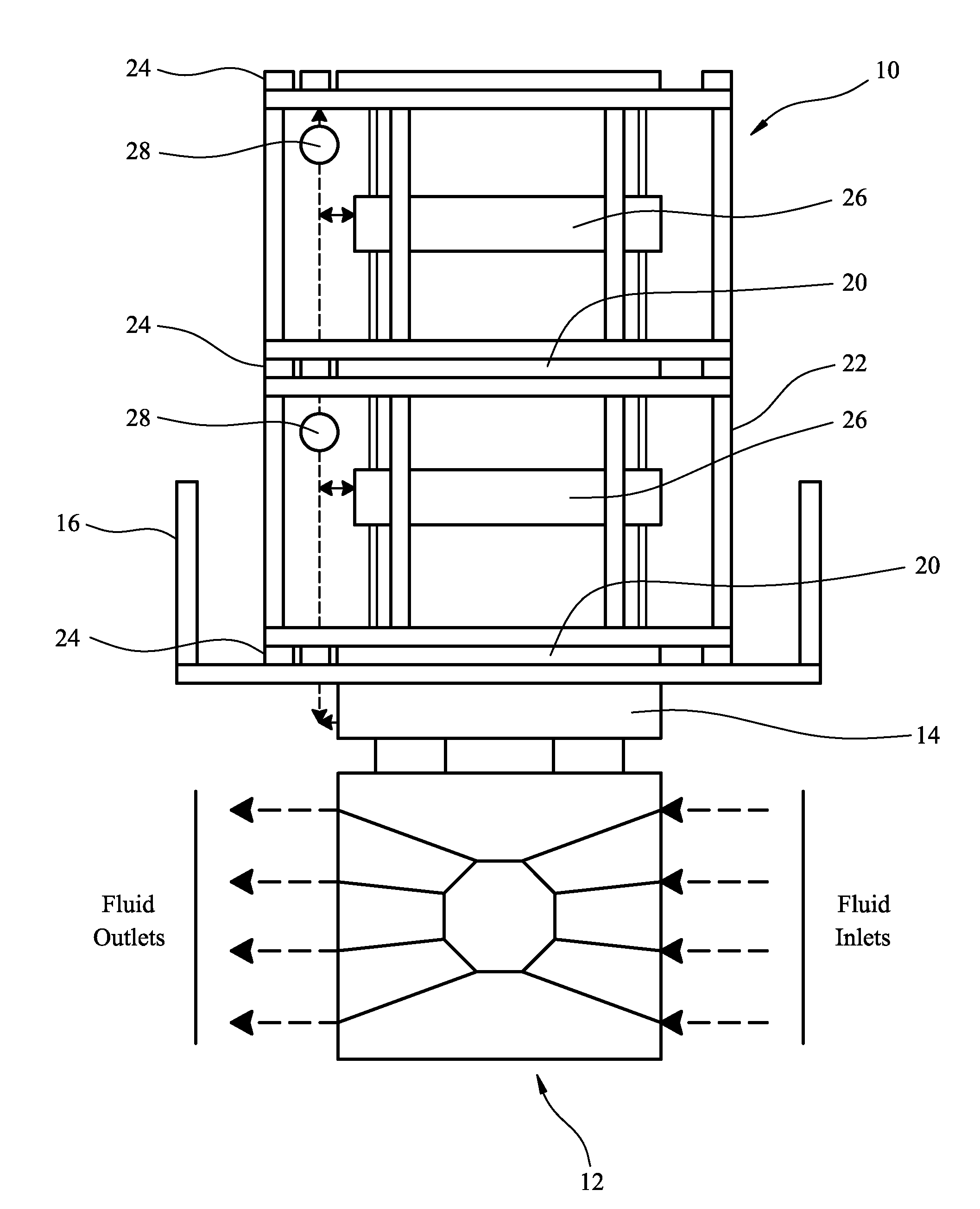
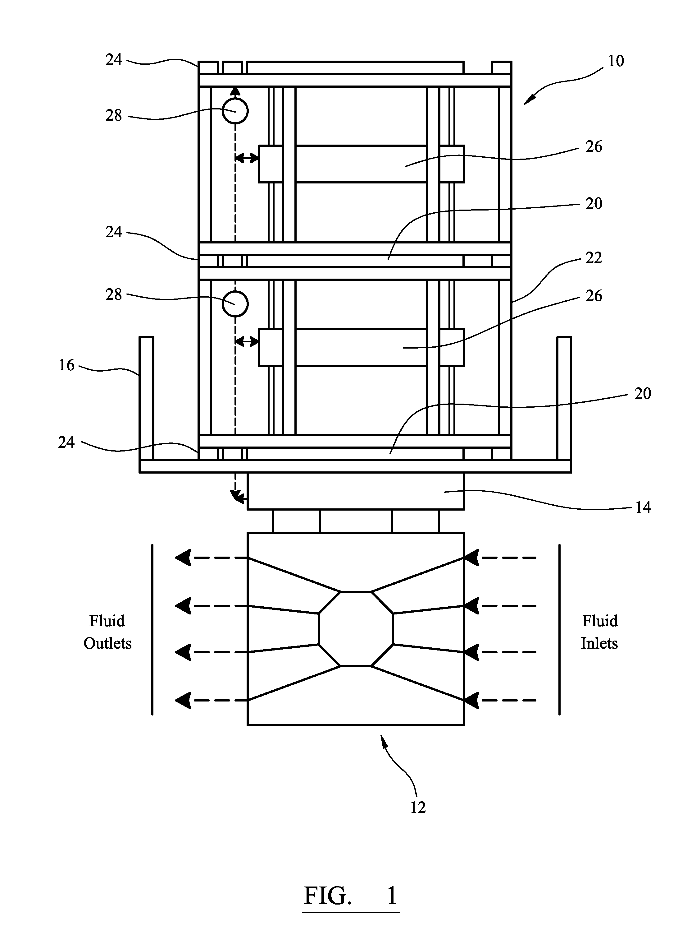
[0049]This subsea apparatus for analysing and / or sampling fluid from a well according to the invention is applicable to subsea installations or facilities in the oil and gas industry. In the drawings FIG. 1 illustrates the basic layout of a subsea apparatus 10 for sampling and / or analysing fluid from a well according to the invention. Subsea apparatus 10 is located in close proximity to the wellhead of a well and includes a subsea fluid processing device 12 for processing fluid samples obtained from the well. The subsea processing device 12 can be a phase separator, a phase accumulator, a boosting pump, a water treatment unit, chemical injector or an injection pump, depending on the application required.

[0050]The subsea processing device 12 includes a fluid sampling device 14. The fluid sampling device 14 consists of a network of pipes connected to different sampling points in the processing device 12. The fluid sampling device 14 can also include a distributor that can redirect the...


PUM


Abstract

Subsea apparatus and a method for sampling and analysing fluid from a subsea fluid flowline proximate a subsea well is provided, wherein the apparatus comprises at least one housing located in close proximity to said subsea fluid flowline; at least one fluid sampling device located in the housing in fluid communication with a said subsea fluid flowline for obtaining a sample of fluid from the subsea fluid flowline; at least one fluid processing apparatus located in the housing in fluid communication with said subsea fluid flowline for receiving and processing a portion of the fluid flowing through said fluid flowline or in fluid communication with the fluid sampling device, for processing the sample of fluid obtained from the subsea fluid flowline for analysis, while keeping the sample of fluid at subsea conditions; a fluid analysis device located in the housing, the fluid analysis device being in fluid communication with the fluid processing device and/or with the fluid sampling device, the fluid analysis device being used for analysing said sample of fluid or the processed sample of fluid to generate data relating to a plurality of properties of said sample of fluid and communicating said data to a surface data processor or to at least one other subsea apparatus; and conveying means included in the housing for conveying the housing means from one subsea fluid flowline to another subsea fluid flowline or for conveying the housing to the surface.

Description

BACKGROUND OF THE INVENTION[0001]This invention relates to subsea apparatus for fluid sampling and / or analysis. In particular, the invention relates to a subsea apparatus for fluid sampling and / or analysis used in the oil and gas industry.[0002]Understanding the properties of fluids in wells in the oil and gas industry is critical for the assessment of oil or gas reservoirs. For example, the fluid properties may be used for the proper management of oil and gas reservoirs including for instance production management and flow assurance. Fluid sampling and / or analysis may be performed during various phases of the exploration, development and production phases of a reservoir. Conventional tools are able to take a fluid sample from the well and bring it to surface where it is processed and analysed. For example, often times the phase behavior of the fluid may be studied using an analysis known in the industry as PVT analysis which measures, inter alia, the bubble point of the fluid as we...

Claims


Application Information

Patent Timeline
Patent Type & Authority Applications(United States)
IPC IPC(8): E21B49/08E21B43/36E21B41/04
CPCE21B41/04E21B49/086E21B49/081E21B33/03E21B49/08
Inventor VANNUFFELEN, STEPHANEVASQUES, RICARDOYAMATE, TSUTOMUKAMIYA, AKIRAINDO, KENTAROODDIE, GARYMACHIN, JONATHANMORGAN, JULIESTENHAUG, MORTENBIRKETT, GRAHAMMULLINS, OLIVER C.MANGAL, LARSPANETTA, PASCAL
Owner SCHLUMBERGER TECH CORP
Why Eureka
Try Eureka