Reception device and reception method

a technology of reception device and reception method, which is applied in the direction of television system, selective content distribution, instruments, etc., can solve the problems of image burn-in, drop in luminance, ghosting, etc., and achieve the effect of preventing image burn-in

Inactive Publication Date: 2010-03-11
PANASONIC CORP
View PDF13 Cites 55 Cited by
  • Summary
  • Abstract
  • Description
  • Claims
  • Application Information

AI Technical Summary

Benefits of technology

[0011]The present invention is directed to solving the foregoing problem, and a reception device and reception method according to the present invention preven

Problems solved by technology

When an OCAP application window containing such a fixed image is displayed for an extended period of time on a plasma display panel, however, an image retention problem sometimes also referred to as image burn-in may occur.
The plasma discharge state of a plasma display panel changes according

Method used


Image

  • Reception device and reception method
  • Reception device and reception method
  • Reception device and reception method

Examples


embodiment 1

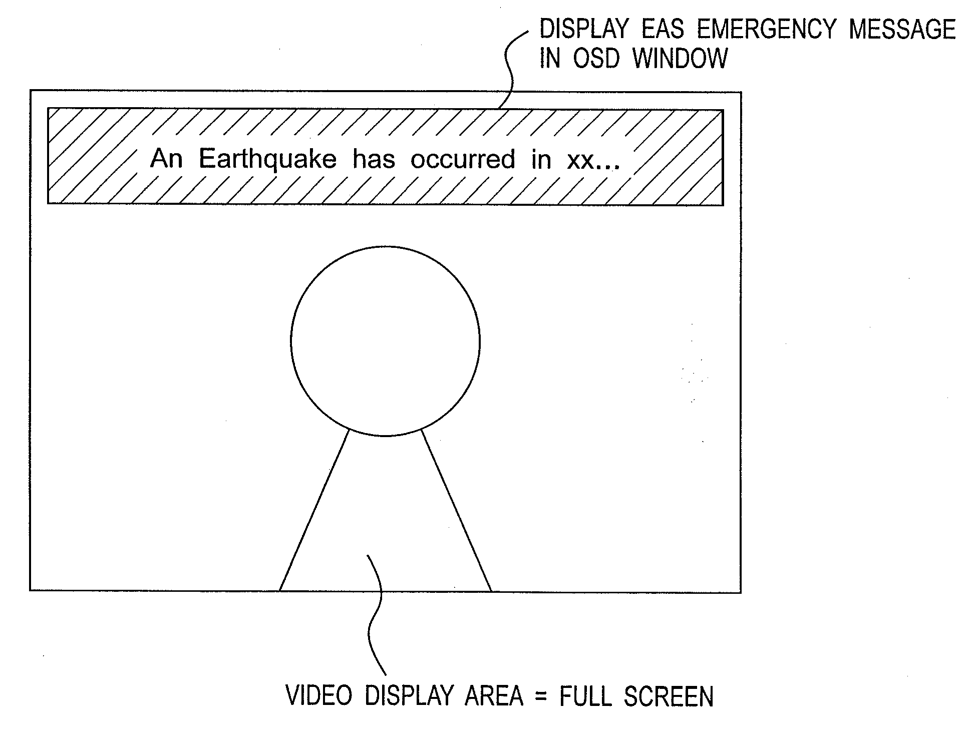
[0077]A reception device according to a first embodiment of the invention prevents image retention or burn-in on a plasma display panel (PDP) by using a screen saver. A first novel aspect of this first embodiment of the invention relates to the configuration that starts the screen saver operation, and second novel aspect of the invention relates to implementing this screen saver function.

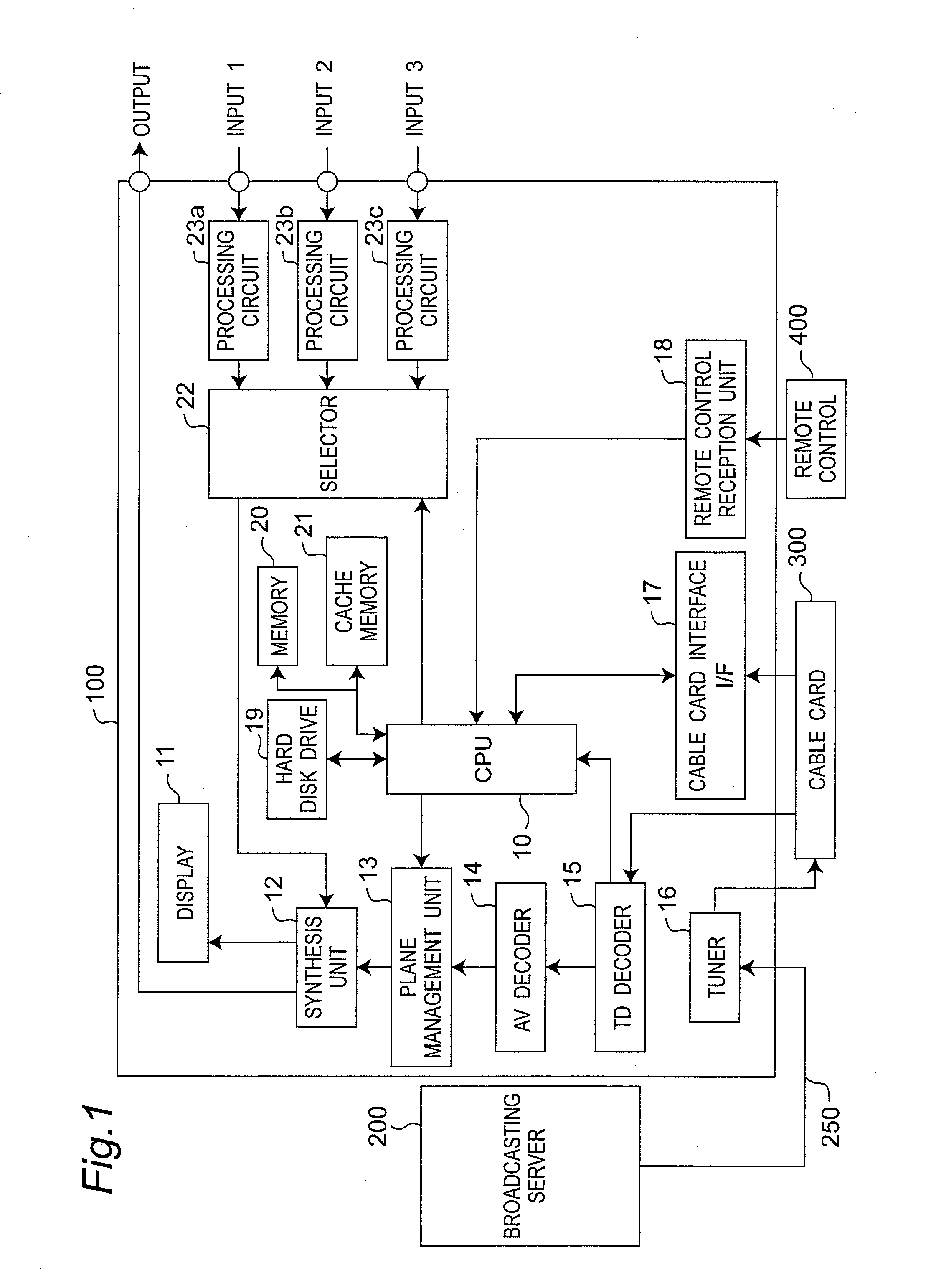
[0078]FIG. 1 is a block diagram schematically showing the hardware configuration of a reception device according to this first embodiment of the invention.

[0079]Referring to FIG. 1, a broadcasting server 200 is located in a broadcasting station of the cable company, and delivers cable broadcasts through a cable 250 to individual subscribers (cable broadcast receivers).

[0080]A cable receiver 100 is installed in the home, for example, of each subscriber, and receives cable broadcasts from a particular cable company (broadcaster) through the cable 250 when a particular process is executed using an inse...

embodiment 2

[0162]A second embodiment of the invention is described next with particular attention to how the second embodiment differs from the first embodiment. The screen saver display in the second embodiment of the invention causes the still image containing text or graphic elements (that is, the non-superimposed still information) to move bidirectionally both horizontally and vertically. Other aspects of the configuration, operation, and effect of this embodiment are the same as the first embodiment.

[0163]FIG. 9 shows the operation of the screen saver in the second embodiment of the invention. In FIG. 9 the still image (that is, the circle) is moved bidirectionally only M pixels horizontally (where M is an integer of 1 or more) and N lines (where N is an integer of 1 or more) vertically during the predetermined period T2. As a result, the image does not remain in a fixed location on screen. Other graphics and text can also be moved bidirectionally in the same way. Moving the still image i...

embodiment 3

[0165]A third embodiment of the invention is described next with particular attention to how the third embodiment differs from the first and second embodiments. The screen saver operation in the third embodiment of the invention extracts the horizontal border portion of the still image containing text or graphic elements (that is, the non-superimposed still information) and the background image, and causes this extracted border portion to move bidirectionally horizontally.

[0166]Other aspects of the configuration, operation, and effect of this embodiment are the same as the first and second embodiments.

[0167]While not shown in the figures, one arrangement of extracting this horizontal border portion is to apply a high pass filter operation horizontally to the pixel data on screen. An example of this high pass filter is the operation shown in equation 1 below.

Yn=ABS(Xn+1−Xn)   (1)

where ABS( ) is a function that returns the absolute value, Xn denotes the pixel brightness component, and...


PUM


Abstract

The display information generating unit manages a first plane that contains video information and a second plane that contains first still information and second still information, and merges the first plane and second plane. The control unit adds at least one of the first still information and second still information to the second plane when an interrupt signal is generated. If the display area of the video information is the full display area of the display screen, the control unit starts a screen saver operation that changes the first still information after a first predetermined period from a time point of the interrupt signal. If the display area of the video information is smaller than the full display area of the display screen, the control unit starts a screen saver operation that changes the second still information after a second predetermined period from a time point of the interrupt signal.

Description

BACKGROUND OF THE INVENTION[0001]1. Field of Invention[0002]The present invention relates to a reception device and a reception method for receiving cable television broadcasts, for example, and relates more particularly to a reception device and a reception method that are used in a flat panel display device such as a plasma display panel (PDP).[0003]2. Description of Related Art[0004]Conversion to digital broadcasts continues in the cable television industry, and a variety of services are now available. Various technologies have also been developed for the reception devices used to receive cable broadcasts. See, for example, U.S. Patent Application Publication No. 2004 / 0107451. One such technology is the Open Cable Application Platform (OCAP) that has been proposed as a standard specification for next-generation cable broadcasting services and devices in North America.[0005]OCAP enables a cable broadcasting reception system including a television and set-top box, for example, to d...

Claims


Application Information

Patent Timeline
IPC IPC(8): H04N5/445H04N7/025H04N5/00H04N5/45
CPCG09G5/14H04N21/4882G09G2320/066G09G2330/021G09G2330/04G09G2340/12G09G2340/125H04N5/44513H04N5/44591H04N5/45H04N21/4181H04N21/431H04N21/4405H04N21/44213H04N21/4438H04N21/478G09G2320/0626H04N21/4316H04N21/47
Inventor AOKI, HIROSHIYASUHO, TSUNEKISUZUKI, HIDEKAZUIWATA, KEISUKEKANZAKI, YASUNOBU
Owner PANASONIC CORP
Why Eureka
Try Eureka