Lens drive device

a technology of lens drive and drive shaft, which is applied in the direction of dynamo-electric components, dynamo-electric machines, instruments, etc., can solve the problems of constant spring variation and insufficient drive of the moving body

Active Publication Date: 2010-03-11
SANKYO SEIKI MFG CO LTD
View PDF3 Cites 28 Cited by
  • Summary
  • Abstract
  • Description
  • Claims
  • Application Information

AI Technical Summary

Benefits of technology

[0006]In view of the problems described above, at least an embodiment of the present invention may advantageously provide a lens drive dev

Problems solved by technology

However, in the structure that the end part of the spring piece is bent to be drawn outside of the support body as a terminal like the above-mentioned Patent Reference, when the end

Method used


Image

  • Lens drive device
  • Lens drive device
  • Lens drive device

Examples


Embodiment Construction

[0031]An embodiment of the present invention will be described below with reference to the accompanying drawings. A lens drive device which will be described below is capable of being mounted on various electronic apparatuses in addition to a cell phone with a camera. For example, the lens drive device may be mounted on a thin-type digital camera, a PHS, a PDA, a bar code reader, a monitoring camera, a camera for rear confirmation in a car, a door having optical authentication function or the like or any other device.

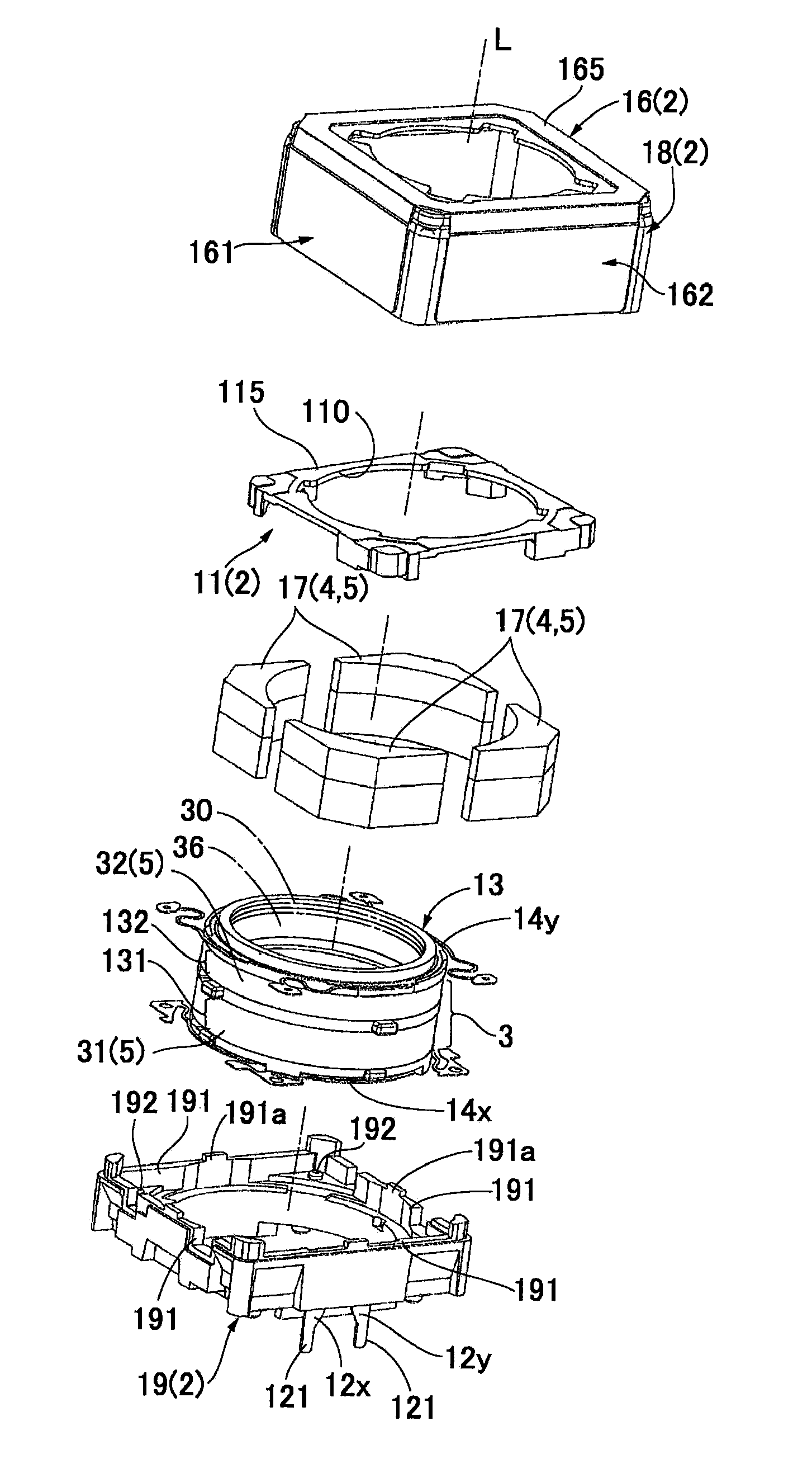
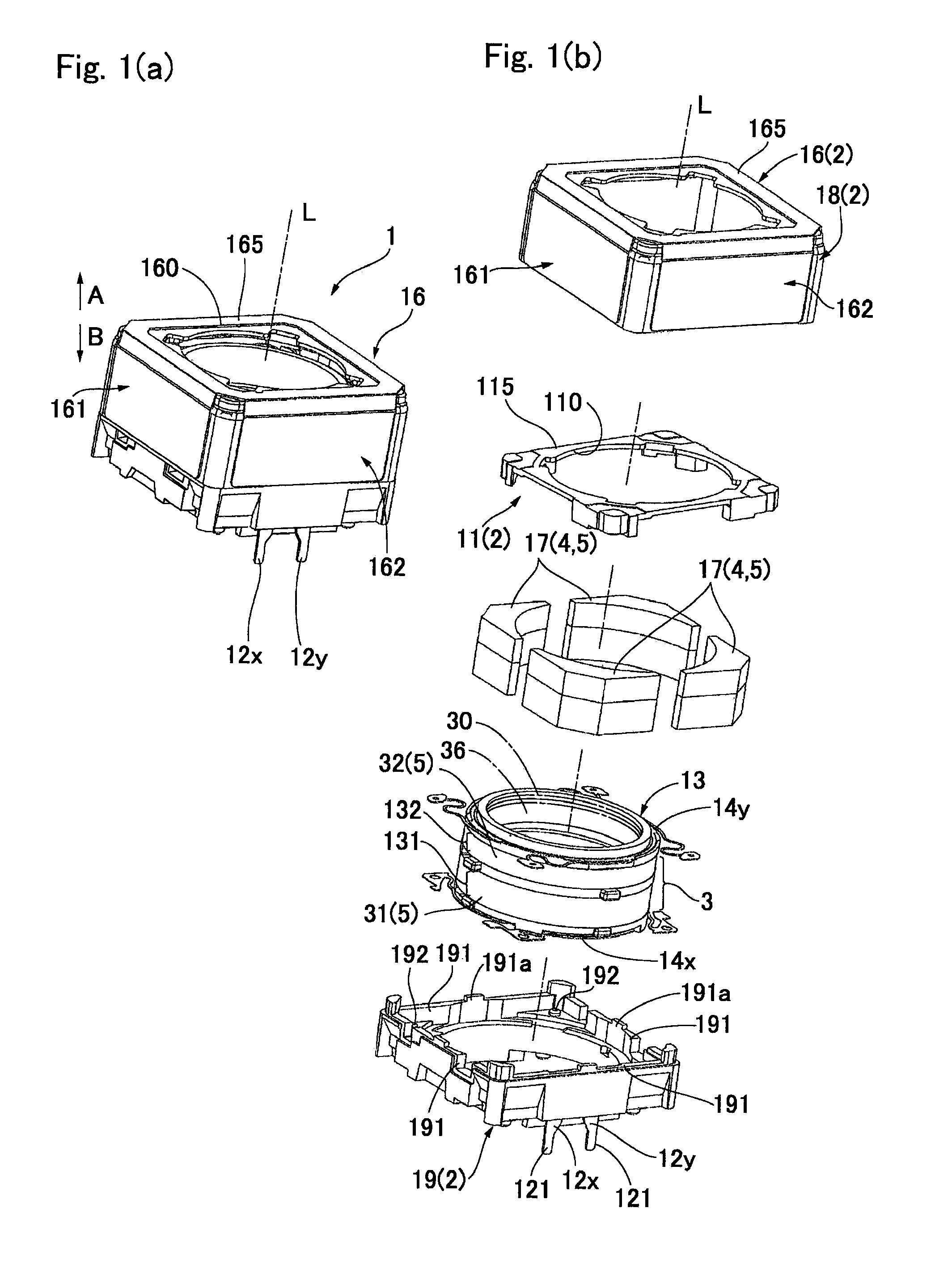
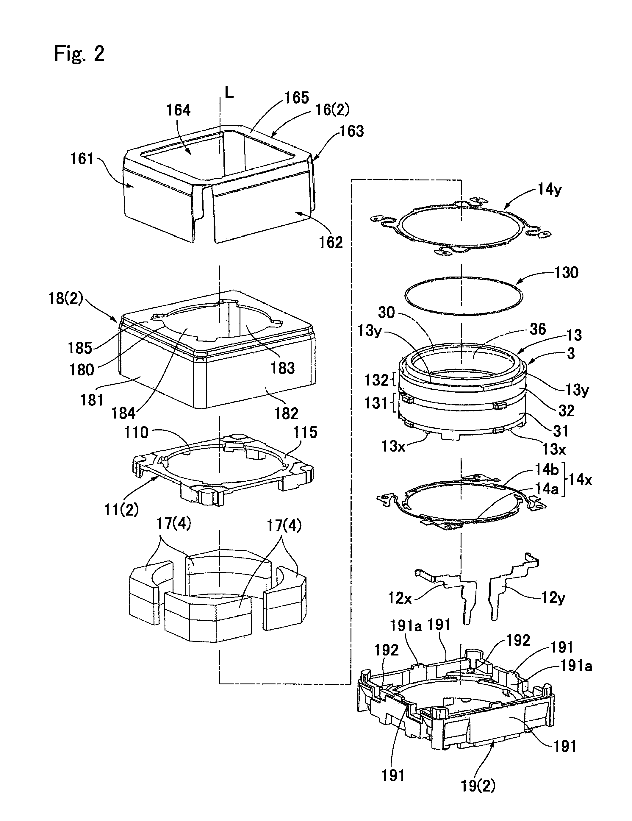
[0032]FIG. 1(a) is an outward appearance view showing a lens drive device in accordance with an embodiment of the present invention which is viewed from obliquely above, and FIG. 1(b) is its exploded perspective view. FIG. 2 is a detail exploded perspective view showing a lens drive device, which is separated in more detail than the state shown in FIG. 1(b), in accordance with an embodiment of the present invention. FIG. 3 is an explanatory view schematically showing an...


PUM


Abstract

A lens drive device may include a support body, a movable body having a lens, a magnetic drive mechanism for magnetically driving the movable body in a lens optical axis direction, and a spring member connected between the support body and the movable body. The magnetic drive mechanism includes a coil held by the movable body and both end parts of the coil are electrically connected to different spring pieces of the spring member through terminals. The support body includes an insulation member which holds the terminals, and each of the terminals includes an outside connecting terminal part which is located on an outer side of the insulation member, and a long elongated connecting part which is extended along an inner wall of the insulation member from the outside connecting terminal part and connected with the spring piece of the spring member.

Description

CROSS REFERENCE TO RELATED APPLICATION[0001]The present invention claims priority under 35 U.S.C. §119 to Japanese Application No. 2008-229695 filed Sep. 8, 2008, the entire contents of which are incorporated herein by reference.FIELD OF THE INVENTION[0002]At least an embodiment of the present invention may relate to a lens drive device in which a coil is held on a movable body having a lens.BACKGROUND OF THE INVENTION[0003]A lens drive device which is mounted on a cell phone with a camera or mounted on a digital camera may include a support body, a movable body having a lens, a magnetic drive mechanism for magnetically driving the movable body in an optical axis direction of the lens, and a spring member which is connected between the support body and the movable body. The movable body is driven in the optical axis direction by utilizing a thrust force of the magnetic drive mechanism and an urging force of the spring member. Therefore, in the lens drive device, an electric current ...

Claims


Application Information

Patent Timeline
IPC IPC(8): G02B7/04
CPCG02B7/08H02K41/0356H01F7/066
Inventor HIGUCHI, DAISUKE
Owner SANKYO SEIKI MFG CO LTD
Why Eureka
Try Eureka