

Electronic device
- Summary
- Abstract
- Description
- Claims
- Application Information
AI Technical Summary
Benefits of technology
Problems solved by technology
Method used
Image

Examples
first embodiment
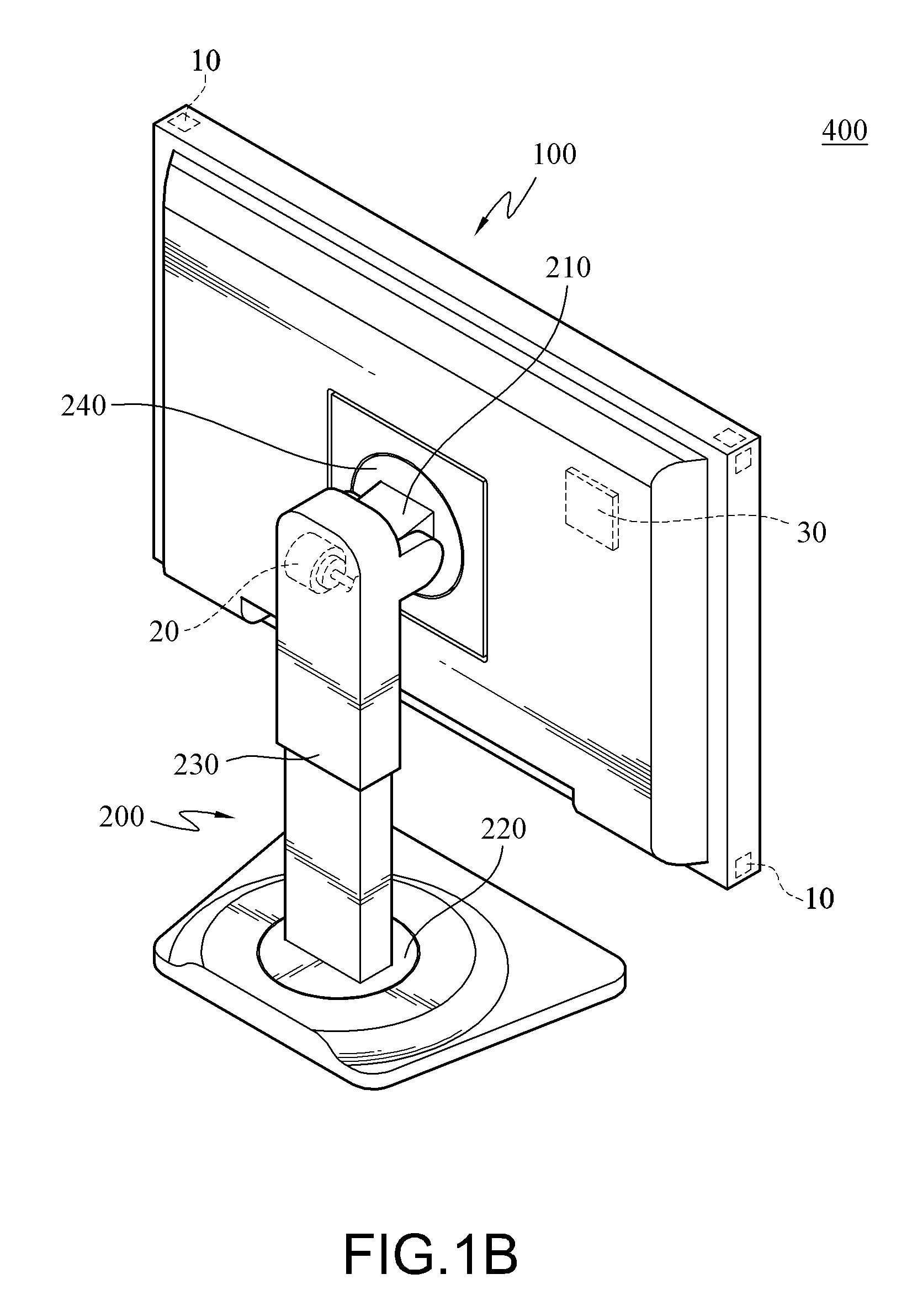
[0037]FIG. 2 is a schematic view illustrating a horizontal rotation in the The specific members may refer to FIGS. 1A and 1B. The rotary motor 20 is located in the base unit 200, and the first rotational structure 220 is movably connected to the display unit 100 and the base unit 200. The rotary motor 20 controls the first rotational structure 220 to drive the display unit 100 to perform a horizontal rotation with the base unit 200 as a support (i.e., the telescopic stand 230) or a rotation axis R1, i.e., to perform the horizontal rotation about the base unit 200, and the rotation angle thereof is in a range of 0° to 180° or 0° to 90°. Further, as shown in the figure, the rotation axis R1 is parallel to the telescopic stand 230.
[0038]FIG. 3 is a schematic view illustrating a vertical rotation in the first embodiment. The rotary motor 20 is located in the base unit 200, and the pivoting structure 210 is movably connected to the display unit 100 and the base unit 200. The rotary moto...
second embodiment
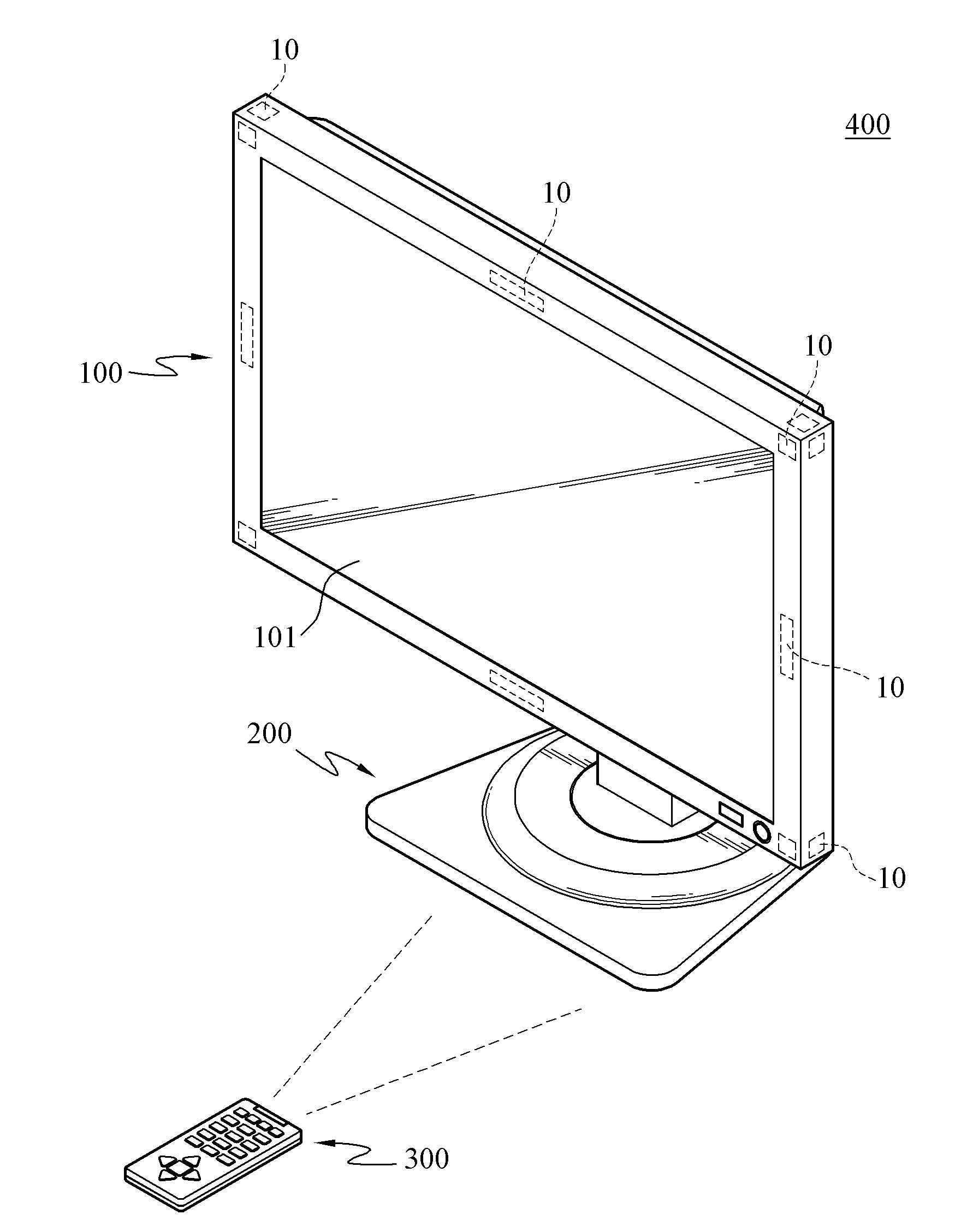
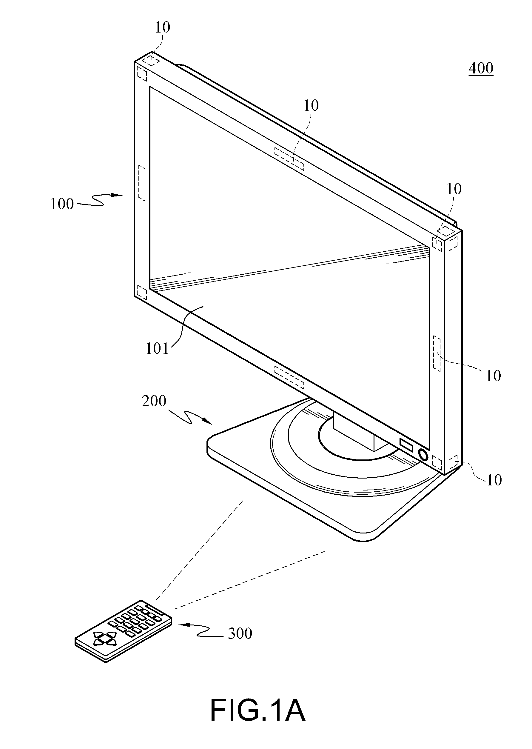
[0043]In this embodiment, the display unit 100 is regarded as an electronic member or can be replaced by other electronic members. FIG. 6 is a schematic view illustrating a horizontal rotation in the A plurality of sensors 10 is disposed on the periphery of the screen 101 of the display unit 100. The sensors 10 can be mounted on one side of the screen 101 or respectively on the left and right sides of the screen 101, and the first rotational structure 220 is movably connected to the display unit 100 and the base 200. When the user touches the sensor 10 on the left or right side of the display unit 100 by hand or by other objects, the sensor 10 receives the user instruction to generate and transmit a touch signal to the microprocessor 30, and then the microprocessor 30 controls the rotary motor 20 to operate. The rotary motor 20 controls the first rotational structure 220 to drive the display unit 100 to perform the horizontal rotation with the base unit 200 as a support (i.e., the ...
PUM
 Abstract
Description
Claims
Application Information