Method and system for encoding a data matrix and method and system for decoding an encoded data matrix

Active Publication Date: 2010-03-11
AGENCY FOR SCI TECH & RES
View PDF2 Cites 1 Cited by
  • Summary
  • Abstract
  • Description
  • Claims
  • Application Information

AI Technical Summary

Problems solved by technology

However, channel state information estimation for the downlink channel at a base-station is not possible in communication systems using FDD (frequency division duplexing), and it is also not straight forward in communication systems using TDD (time division duplexing) due to the mismatch in the radio frequency front end.
This, unfortunately, requires a high feedback bandwidth.

Method used


Image

  • Method and system for encoding a data matrix and method and system for decoding an encoded data matrix
  • Method and system for encoding a data matrix and method and system for decoding an encoded data matrix
  • Method and system for encoding a data matrix and method and system for decoding an encoded data matrix

Examples


Embodiment Construction

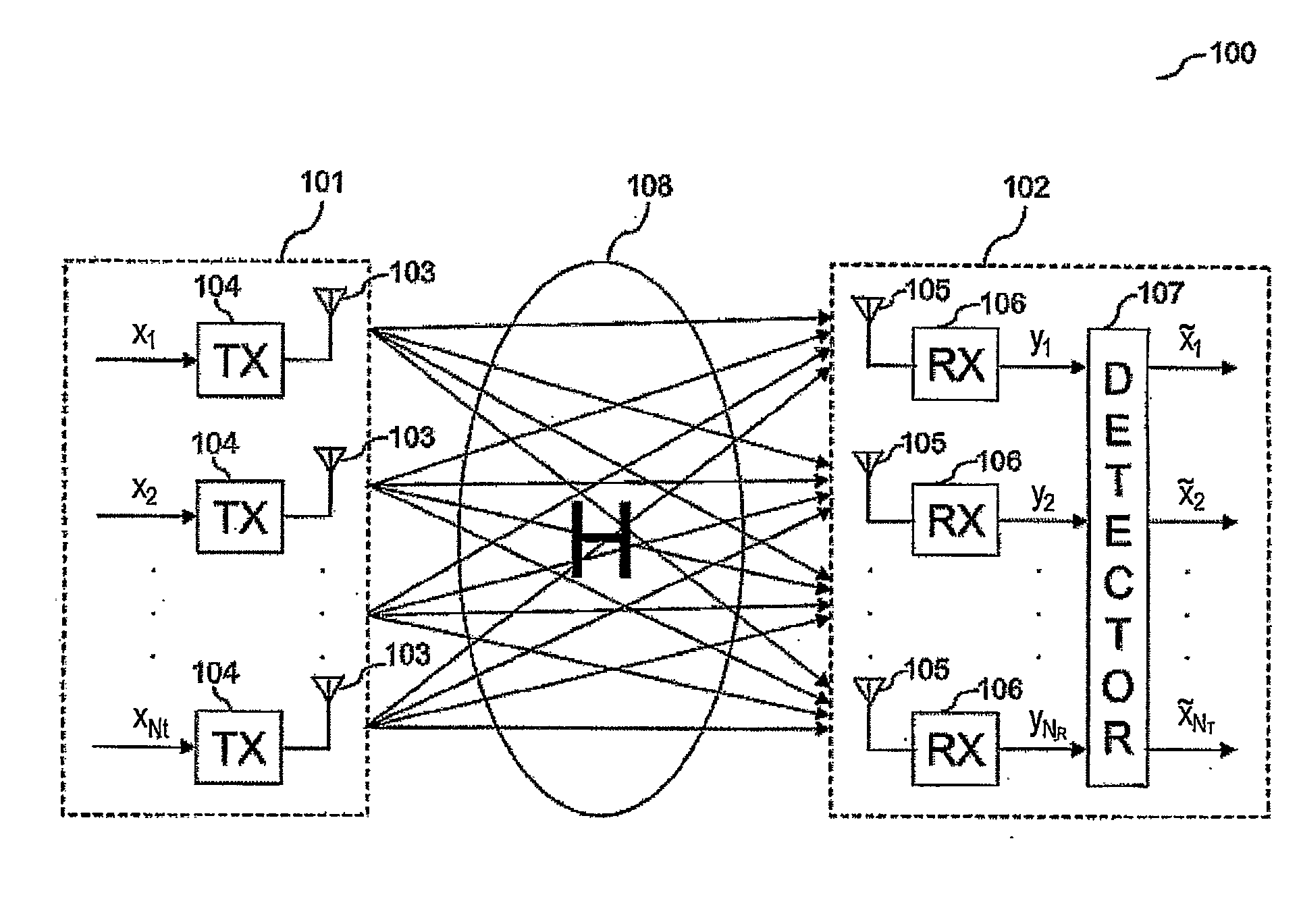
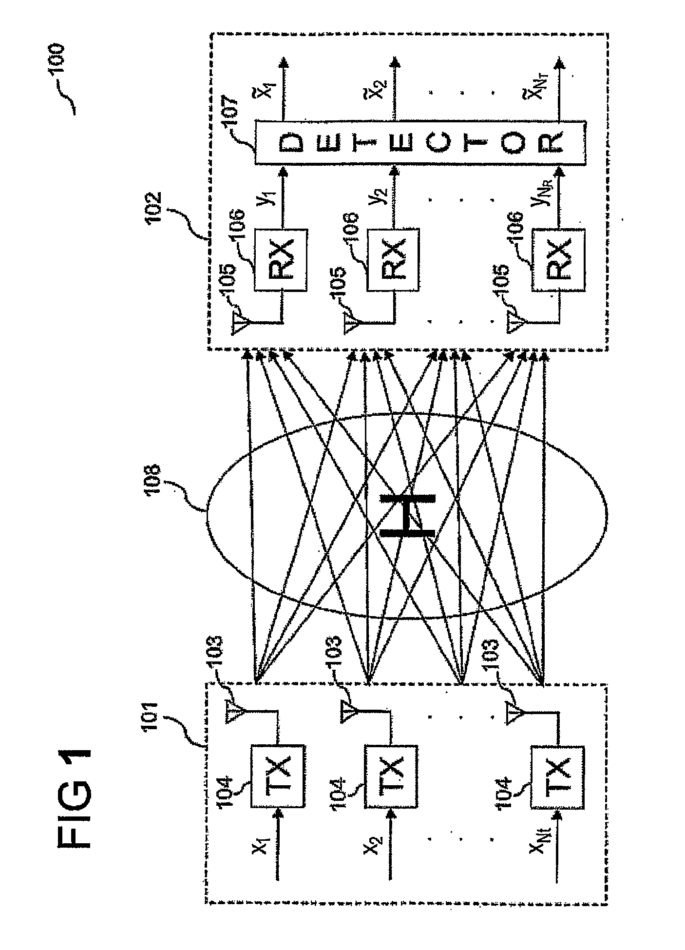
[0012]FIG. 1 shows a communication system 100 according to an embodiment of the invention.

[0013]The communication system 100 includes a transmitter 101 and a receiver 102. The transmitter 101 includes a plurality of transmit antennas 103, each transmit antenna 103 being coupled with a respective sending unit 104.

[0014]Each sending unit 104 is supplied with a component of a NT×1 signal vector x=[1, x2, . . . , xNT]T where NT is the number of transmit antennas 103. Each sending unit 104 transmits the respective component of the signal vector x using the respective antenna 103, such that altogether, the signal vector x is sent. The transmitted signal vector is received by the transmitter 102 by a plurality of receive antennas 105, each receive antenna 105 being coupled with a respective receiving unit 106, in form of the received NR×1 signal vector y=[y1, y2, . . . , yNR]T via a communication channel 108. NR denotes the number of receive antennas 105.

[0015]Since NR and NT are assumed t...


PUM


Abstract

According to one embodiment of the invention, a method for encoding a data matrix having at least a first component and a second component is provided wherein the value of the first component is determined, the number of bits to be used for encoding the second component is selected based on the value of the first component, the second component is encoded using the selected number of bits, and the first component is encoded.

Description

FIELD OF THE INVENTION[0001]Embodiments of the invention generally relate to a method and a system for encoding a data matrix and a method and a system for decoding an encoded data matrix.BACKGROUND OF THE INVENTION[0002]According to the Multiple-input Multiple-output (MIMO) communication technology, multiple transmit antennas of a transmitter and multiple receive antennas of a receiver are used for the transmission of a data stream from the transmitter to the receiver. MIMO has been considered in several communication standards in order to achieve a higher throughput. Although open-loop MIMO techniques have already shown to achieve high performance gain, the availability of either full or partial channel state information (CSI) at the transmitter, e.g. a base-station of a mobile communication network, typically leads to additional performance gain and sometimes even complexity reduction. Such closed-loop schemes have been considered in IEEE 802.11n, IEEE 802.16, and 3GPP Long Term ...

Claims


Application Information

Patent Timeline
IPC IPC(8): H04L27/28H04L27/00H04B1/38
CPCH04B7/0417H04B7/0639H04B7/0634
Inventor YUEN, CHAUSUN, SUMEI
Owner AGENCY FOR SCI TECH & RES
Why Eureka
Try Eureka