Flexural disc fiber optic sensor and method of forming same

a fiber optic sensor and flexural disc technology, applied in the field of fiber optic sensors, can solve the problems of poor strain measurement sensitivity and device more susceptible to high-g shock damag

Inactive Publication Date: 2010-03-11
SCHLUMBERGER TECH CORP
View PDF7 Cites 4 Cited by
  • Summary
  • Abstract
  • Description
  • Claims
  • Application Information

AI Technical Summary

Benefits of technology

[0009]The invention provides a flexural disc fiber optic sensor that is suitable for applications requiring high sensitivity measurements while affording protection from high-g shocks that may be experienced by the sensors.
[0010]The invention also provides a flexural disc fiber optic sensor that can be manufactured at small tolerances, and thus is suitable for applications requiring high sensitivity measurements.
[0011]The invention further provides a flexural disc fiber optic sensor that has a compact design suitable for installation in a borehole that traverses an oilfield.
[0012]Accordingly, as discussed in detail below, the fiber optic sensor of the present invention employs at least two flexural discs that are spaced apart from one another along a central axis. A fiber optic coil is affixed to one of the flexural discs. A proof mass is disposed between the flexural discs. A first stop member is disposed between the proof mass and one flexural disc. A second stop member is disposed between the proof mass and the other flexural disc. The first and second stop members are sized to provide space between the proof mass and the corresponding flexural disc to allow for normal motion of the flexural discs, while interfering with movement of the flexural discs to prohibit unwanted extreme motion.
[0013]In the preferred embodiment, the stop members are made of a thermoplastic material and formed by a self-aligned process that provides for accurate sizing of the stop members at small dimensions (e.g., dimensions that provide for operating gaps less than 25 μm).

Problems solved by technology

As a result, the sensitivity of the strain measurements is poor although the frequency response extends to high frequency.
Such additional mass improves the sensitivity of the device, but makes the device more susceptible to damage from high-g shocks.
Disadvantageously, the shear and compression dampers of the '418 patent are difficult to manufacture at small tolerances, and thus are impractical in applications requiring significant proof mass for high sensitivity measurements.

Method used


Image

  • Flexural disc fiber optic sensor and method of forming same
  • Flexural disc fiber optic sensor and method of forming same

Examples


Embodiment Construction

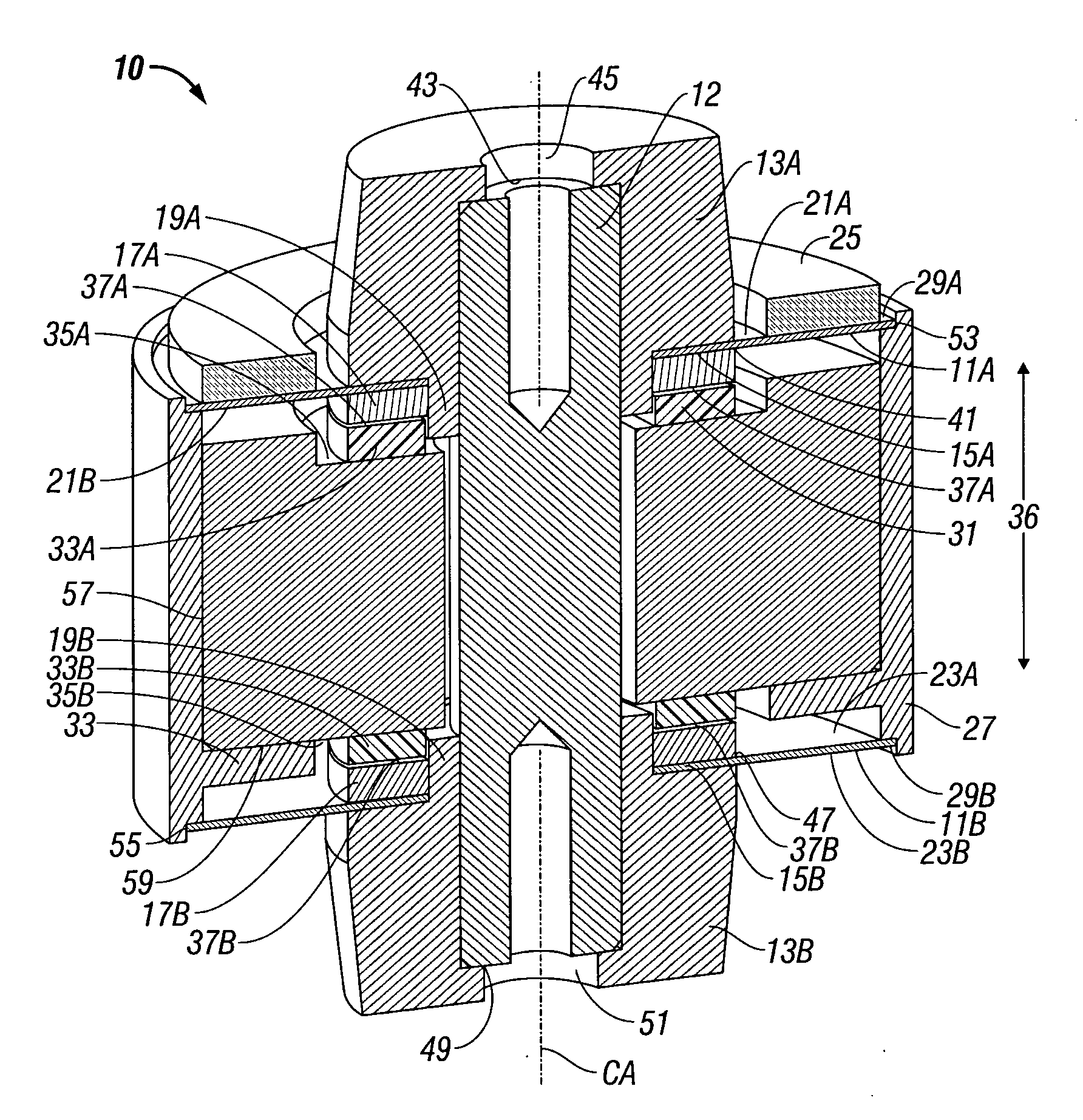
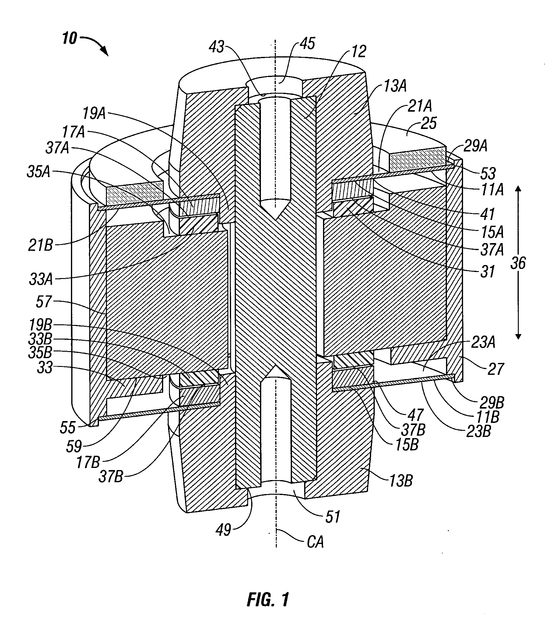
[0018]Turning now to FIG. 1, a fiber optic sensor 10 according to the present invention includes a top flexural disc 11A and a bottom flexural disc 11B that are rigidly attached to a central support structure (e.g., the center post 12 and corresponding central support members13A, 13B). In the preferred embodiment, the radially inner portion 15A of the top flexural disc 11A is permanently affixed between the central support member 13A and a backing disc 17A by welding, adhesive material, or other suitable means (for example, by welding along the interface 41 through the radially inner portion 15A of the top flexural disc 11A to the central support member 13A). The backing disc 17A interfaces to an annular flange portion 19A of the central support member 13A. The central support member 13A is rigidly attached to the center post 12 by welding, adhesive material, or other suitable means (for example, by welding along an interface 43 that is exposed by a cutout 45 in the top wall of the ...


PUM

PropertyMeasurementUnit
temperatureaaaaaaaaaa
heat-deflection temperatureaaaaaaaaaa

Abstract

A fiber optic sensor employs at least two flexural discs that are spaced apart from one another along a central axis. A fiber optic coil is affixed to at least one of the flexural discs. A proof mass is disposed between the flexural discs. A first stop member is disposed between the proof mass and one flexural disc. A second stop member is disposed between the proof mass and the other flexural disc. The first and second stop members are sized to provide space between the proof mass and the corresponding flexural disc to allow for normal motion of the flexural discs, while interfering with movement of the flexural discs to prohibit unwanted extreme motion. The fiber optic sensor can be used for OTDR measurements of acceleration for real-time oilfield monitoring applications as well as other fiber-based interferometric measurement applications. A coupling structure preferably couples the outer edges of the flexible disks, the mass being attached to the coupling structure.

Description

BACKGROUND OF THE INVENTION[0001]1. Field of the Invention[0002]This invention relates broadly to fiber optic sensors for measuring linear acceleration. More particularly, this invention relates to fiber optic sensors that employ an optical fiber coil affixed to a flexural disc.[0003]2. Description of Related Art[0004]The flexure or strain of an optical fiber coil affixed to a flexible disc is a well-known basis for measuring acceleration resulting from momentum forces acting on the disc in a direction normal to the disc. The amount of flexure is determined interferometrically, where interferometric measurements of strain in the optical fiber coil provide high resolution, high data rates, require low power, are immune to electromagnetic interference, and can readily be adapted for remote sensing and / or rugged applications.[0005]The mass which provides the inertia, and hence the force to cause flexure of the disc, usually consists of the disc itself and the optical fiber coil affixed...

Claims


Application Information

Patent Timeline
Patent Type & Authority Applications(United States)
IPC IPC(8): G02B6/00B23P11/02
CPCG01H9/004Y10T29/49865G01V1/181G01P15/093
Inventor BRADY, DOMINIC
Owner SCHLUMBERGER TECH CORP
Why Eureka
Try Eureka