Safety needle assembly and methods

a needle and needle technology, applied in the field of safety needle assembly and methods, can solve the problems of leaving the tip exposed, medical staff will accidentally prick themselves,

Active Publication Date: 2010-03-11
B BRAUN MEDICAL
View PDF101 Cites 34 Cited by
  • Summary
  • Abstract
  • Description
  • Claims
  • Application Information

AI Technical Summary

Problems solved by technology

It is disadvantageous to leave the tip exposed, as there is a risk that medical staff will accidentally prick themselves.

Method used


Image

  • Safety needle assembly and methods
  • Safety needle assembly and methods
  • Safety needle assembly and methods

Examples


Embodiment Construction

,” one will understand how the features of the present embodiments provide advantages, which include reliable covering of the sharp needle tip.

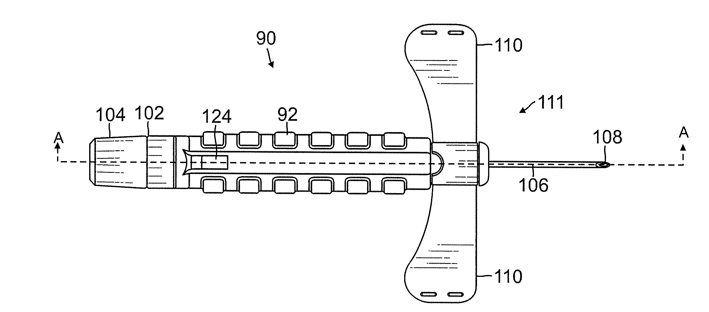
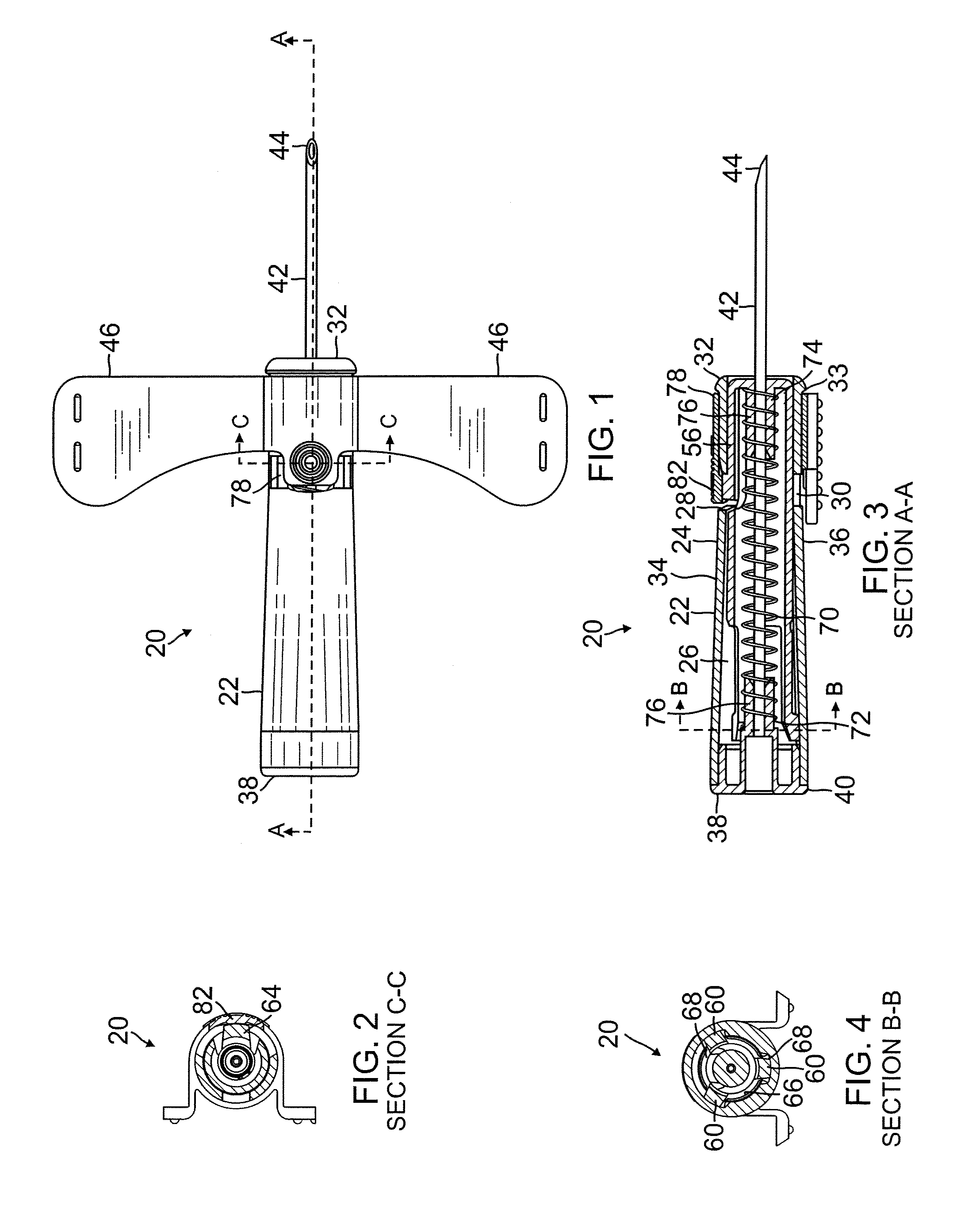
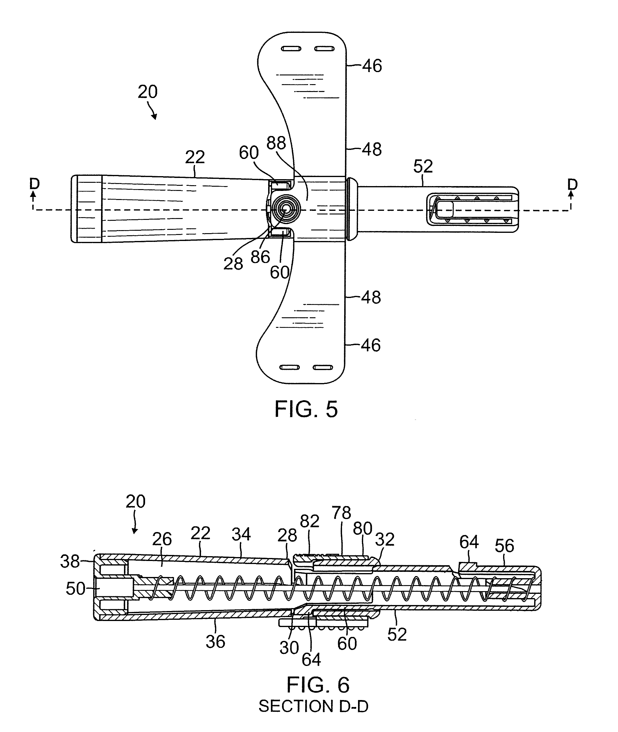
[0005]One embodiment of the present safety needle assembly comprises an elongate body including a body wall defining an internal passageway and including an opening in the body wall. The assembly further comprises a needle hub engaging a proximal end of the body and being stationary with respect to the body. The assembly further comprises a needle extending distally from the needle hub and through the body internal passageway. The needle includes a sharp distal tip. A needle shield is disposed within the body internal passageway and surrounds a portion of the needle. The needle shield is slidable with respect to the body and with respect to the needle. A biasing element engages the needle shield and biases the needle shield toward a distal end of the needle. A release latch extends from the needle shield. The release latch comprises a leaf sp...


PUM

PropertyMeasurementUnit
pressureaaaaaaaaaa
compressive forceaaaaaaaaaa
diameteraaaaaaaaaa

Abstract

Embodiments of the present safety needle assembly include a slidable needle shield. Digital pressure applied to a leaf spring retention latch removes a compressive force from a biasing member and automatically moves the needle shield from a ready-to-use configuration to a protected configuration in which the needle shield covers the sharp needle tip. In the protected configuration the needle shield is prevented from sliding proximally along the needle a sufficient distance to expose the needle tip.

Description

CROSS-REFERENCE TO RELATED APPLICATION[0001]This is a regular utility application of provisional application Ser. No. 61 / 095,716, filed Sep. 10, 2008, the contents of which are expressly incorporated herein by reference for all purposes.BACKGROUND[0002]The present invention relates to apparatus and methods for percutaneously infusing fluids to a body and / or withdrawing fluids from a body.Description of Related Art[0003]Needle assemblies are commonly used to percutaneously infuse fluids to a body and / or withdraw fluids from a body. The needle assembly generally remains disposed in the vasculature while one or more assemblies are connected and disconnected to the assembly to complete the infusion / withdrawal process. Upon withdrawing the assembly from the vasculature, the sharp distal tip of the needle is exposed. It is disadvantageous to leave the tip exposed, as there is a risk that medical staff will accidentally prick themselves. This phenomenon is known as needlestick. and can tra...

Claims


Application Information

Patent Timeline
Patent Type & Authority Applications(United States)
IPC IPC(8): A61M5/32B23P11/00
CPCA61M5/3257A61M5/3271Y10T29/49826A61M2005/3247A61M25/0637
Inventor MOYER, SCOTT A.JANDERS, MICHAEL J.
Owner B BRAUN MEDICAL
Why Eureka
Try Eureka