
Gas sensor fitting structure

a technology of gas sensor and fitting structure, which is applied in the direction of machines/engines, instruments, exhaust treatment electric control, etc., can solve the problems of reducing the possibility and reducing so as to minimize the occurrence of cracks in the sensor element and suppress the entry of condensed water

Active Publication Date: 2010-03-18
TOYOTA JIDOSHA KK
View PDF7 Cites 6 Cited by
  • Summary
  • Abstract
  • Description
  • Claims
  • Application Information

AI Technical Summary

Benefits of technology

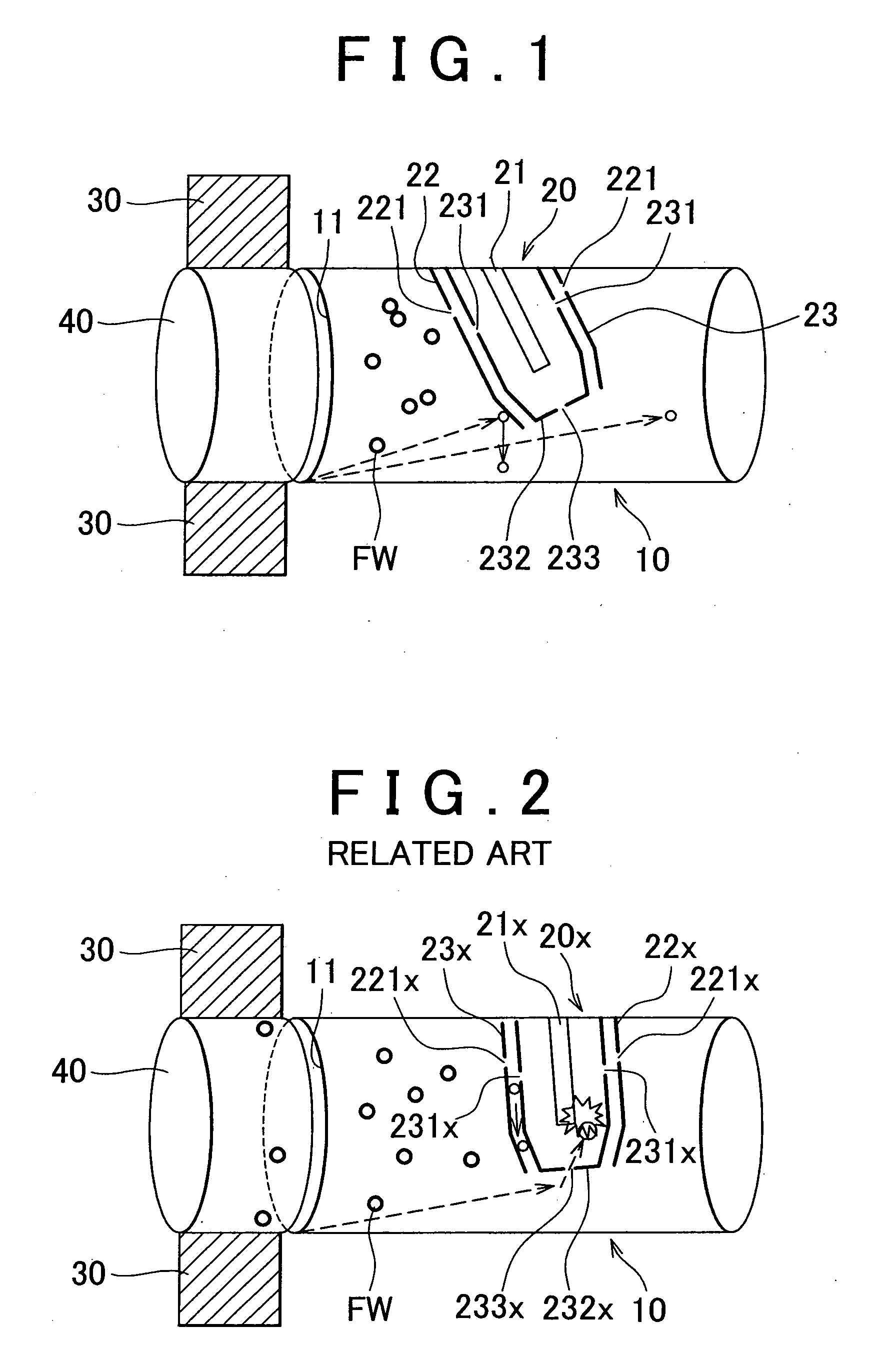
[0007]The invention provides a gas sensor fitting structure which makes it possible to suppress entry of condensed water into a cover and to minimize occurrence of a crack in a sensor element due to contact of the condensed water with the sensor element.
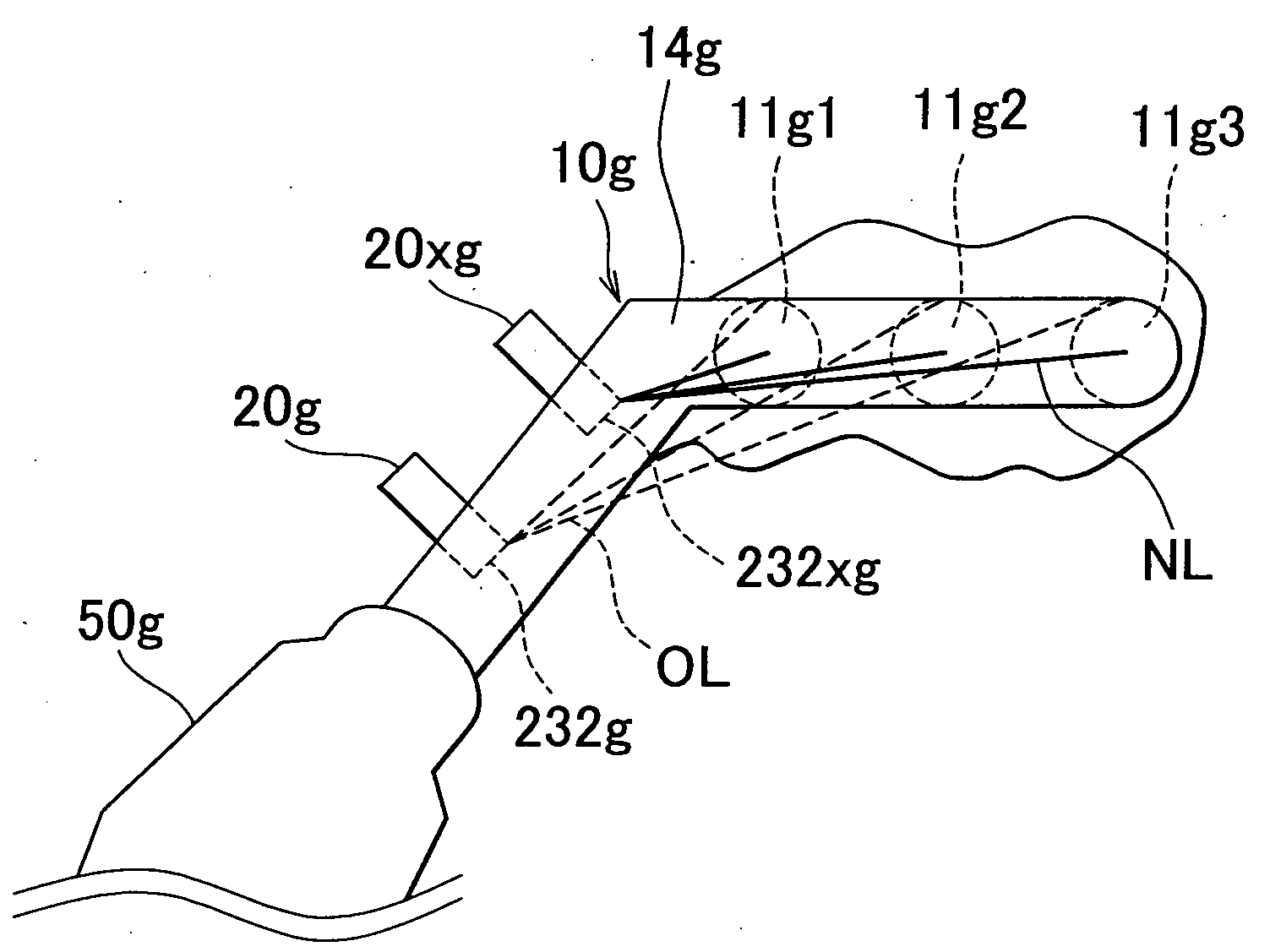
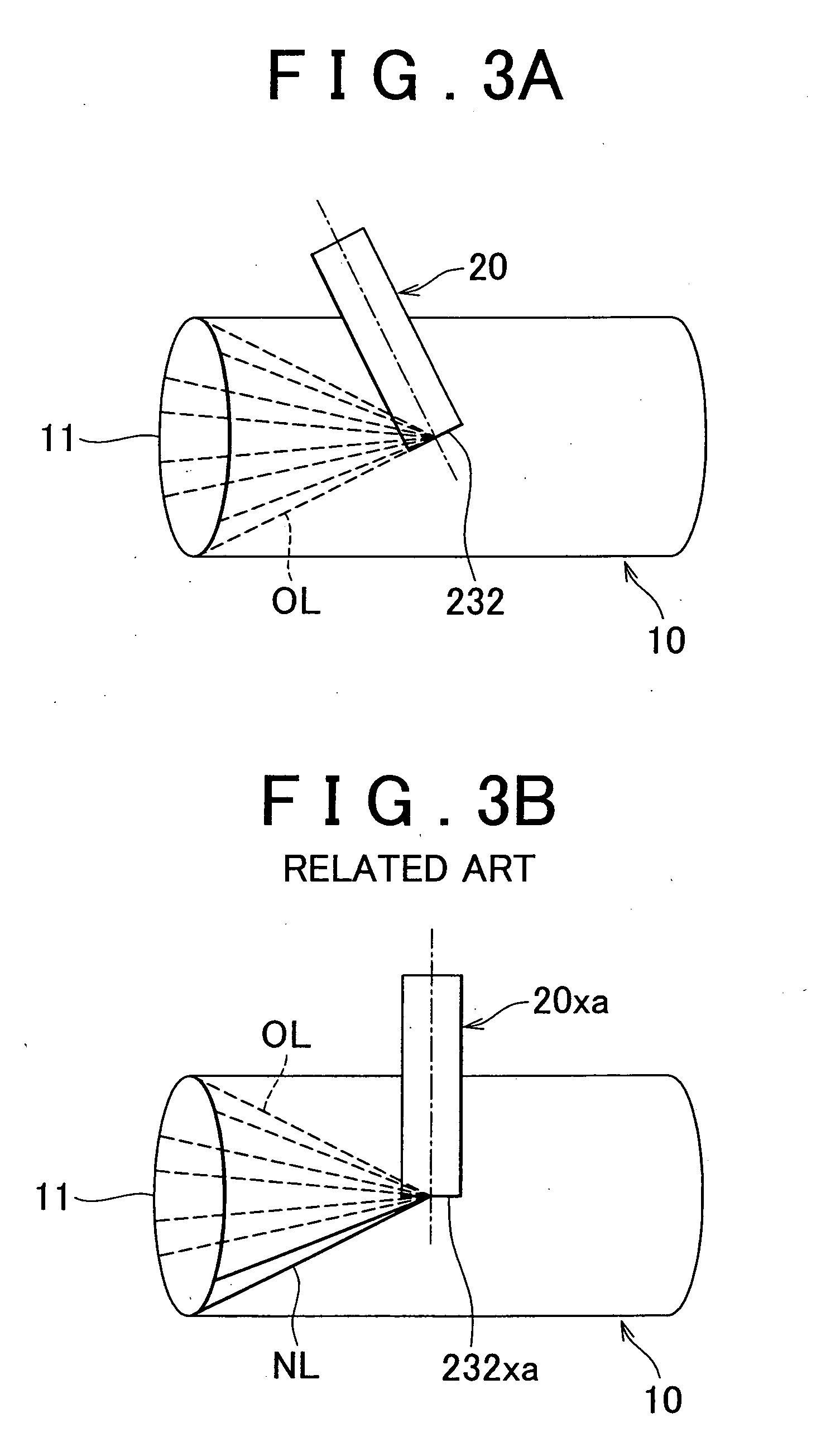
[0008]A first aspect of the invention relates to a gas sensor fitting structure for fitting a gas sensor to an exhaust pipe of an internal combustion engine, and the gas sensor includes a sensor element and a cover which covers the sensor element, and has a vent-hole at an end portion of the cover. The exhaust pipe has multiple inlet portions, and the gas sensor is fitted to the exhaust pipe at a predetermined fitting angle so that the end portion is not visible from any position of the multiple inlet portions. With this fitting structure, it is possible to suppress entry of the condensed water into the cover through the vent-hole formed in the end portion of the cover. Thus, it is possible to minimize occurrence of a crack in the sensor element due to contact of the condensed water with the sensor element.
[0009]A second aspect of the invention relates to a gas sensor fitting structure for fitting a gas sensor to an exhaust pipe of an internal combustion engine, and the gas sensor includes a sensor element and a cover which covers the sensor element, and has a vent-hole at an end portion of the cover. The exhaust pipe has a bent portion, and the gas sensor is fitted to the exhaust pipe at a predetermined fitting angle so that the end portion is not visible via the bent portion from any position of an inlet portion of the exhaust pipe. With this fitting structure as well, it is possible to suppress entry of the condensed water into the cover through the vent-hole formed in the end portion of the cover.
[0015]The inlet portion of the exhaust pipe may be connected to an exhaust port of the internal combustion engine, and the predetermined fitting angle of the gas sensor with respect to the exhaust pipe may be decreased as the distance between the inlet portion and the gas sensor decreases.

Problems solved by technology

This fitting structure reduces the possibility that foreign matter contained in the fluid in the cover will adhere to a sensor element.
If the condensed water contacts a sensor element while the sensor element is heated by a heater, a crack may occur in the sensor element.

Method used


Image

  • Gas sensor fitting structure
  • Gas sensor fitting structure
  • Gas sensor fitting structure

Examples


first embodiment

[0029]Hereafter, the invention will be described with reference to the accompanying drawings.

[0030]FIG. 1 is a view showing a gas sensor fitting structure according to the first embodiment of the invention. A gas sensor 20 according to the first embodiment of the invention is an air-fuel ratio sensor that linearly detects an air-fuel ratio based on an oxygen concentration in the exhaust gas. However, the gas sensor 20 is not limited to such air-fuel ratio sensor. The gas sensor 20 may be an oxygen sensor that determines whether an air-fuel ratio is richer or leaner than the stoichiometric air-fuel ratio based on an oxygen concentration in the exhaust gas or various gas sensors that detect, for example, a NOx concentration, a CO concentration, and a HC concentration. The gas sensor 20 includes a stacked sensor element 21. Alternatively, the gas sensor 20 may include a cup-shaped sensor element.

[0031]The gas sensor 20 is fitted to an exhaust pipe 10 in such a manner that a portion of ...


PUM


Abstract

A gas sensor is fitted to an exhaust pipe such that an end face in which a vent-hole is formed is not visible from any position of inlet portions of the exhaust pipe. Thus, it is possible to suppress entry of condensed water through the vent hole formed in the end face of the gas sensor. As a result, it is possible to minimize occurrence of a crack in the gas sensor.

Description

BACKGROUND OF THE INVENTION[0001]1. Field of the Invention[0002]The invention relates to a gas sensor fitting structure.[0003]2. Description of the Related Art[0004]In an internal combustion engine, gas sensors such as an air-fuel ratio sensor and an oxygen sensor are fitted to an exhaust pipe. Such gas sensor usually includes a sensor element, a heater that activates the sensor element, and a cover that covers the sensor element. A vent-hole is formed in the cover so that the sensor element is exposed to the exhaust gas that flows into the gas sensor through the vent-hole.[0005]Japanese Patent Application Publication No. 10-148623 (JP-A-10-148623) describes a fluid sensor fitting structure. More specifically, JP-A-10-148623 describes a structure in which a fluid sensor is fitted to a fluid pipe with the central axis of the fluid sensor inclined with respect to the direction that is perpendicular to the direction in which the fluid flows. This fitting structure reduces the possibili...

Claims


Application Information

Patent Timeline
Patent Type & Authority Applications(United States)
IPC IPC(8): F01N11/00
CPCF01N11/00F01N13/008Y02T10/47G01N33/006F01N2560/00Y02T10/40
Inventor GOYA, YOICHIRO
Owner TOYOTA JIDOSHA KK
Learn More