Combined operation and control of suction modulation and pulse width modulation valves

a pulse width modulation and valve technology, applied in the field of refrigerant systems, can solve the problems of reducing the provided capacity and power consumption, discharge temperature exceeding the safe reliability limit, and pressure within the compressor shell may drop to an extremely low value, so as to achieve the effect of high refrigerant flow rate and lower system efficiency

Active Publication Date: 2010-03-18
CARRIER CORP
View PDF12 Cites 5 Cited by
  • Summary
  • Abstract
  • Description
  • Claims
  • Application Information

AI Technical Summary

Benefits of technology

[0008]In a disclosed embodiment of this invention, a second flow path is included into a refrigerant system in parallel to a pulse width modulation controlled suction valve. This second flow path includes a separate suction modulation valve which can be opened to a small and variable degree of opening, when the pulse width modulation controlled valve is closed. Thus, a small amount of refrigerant can pass into the compressor shell, and the compressor shell will not be at an unduly low suction pressure as described above. Additionally by controlling the size of the suction modulation valve (SMV) opening when the pulse width modulation valve is closed, the pressure within the compressor shell can be maintained at constant and most desirable, optimum level, regardless of the operating conditions. Both valves can be relatively small in that they can operate in tandem at higher refrigerant flow rates. Further, the additional suction modulation valve provides a redundant valve which can be switched to being a primary valve should the pulse width modulation valve ever fail. In this case, a failure of the pulse width modulation valve would not lead to unacceptable system performance, as the system capacity would still be controlled by the opening adjustment through the suction modulation valve. Although, under such circumstances, the system efficiency may be lower than with the functioning pulse width modulation valve, operation of the suction modulation valve would still allow the refrigerant system provide necessary capacity control.

Problems solved by technology

Such a blockage of refrigerant flow reduces the provided capacity and power consumption.
One challenge with regard to utilizing pulse width modulation control for a suction valve and reducing the pressure to the lowest possible value, for the purpose of reducing delivered capacity, is that, when the suction valve is in the closed position, to reduce capacity to its minimum, the pressure within a compressor shell may decrease to an extremely low value to be effectively near complete vacuum.
It is undesirable to have a pressure below a minimum predetermined pressure threshold in the compressor shell, as this may sometimes lead to an undesirable condition so-called “corona discharge.” Also, the compressor motor can overheat causing the discharge temperature to be above the specified safe reliability limit.
A “corona discharge” phenomenon can occur over the electrical terminals, and may lead to a deterioration of the terminals, and consequently to compressor failure.
Since it is impossible to change the size of the opening for a fixed size restriction, it leads to less than optimum performance.
This in turn led to lower system efficiency, because the pressure was too high to assure the efficient operation at such “off-design” conditions.
In other words, in the prior art, the pressure could not be controlled to a minimum acceptable level for all operating conditions, while using the fixed size restriction, causing the pressure to be higher than desired for some of the operating conditions, and leading to lower efficiency in these instances.
Also the failure of the pulse width modulated valve, in the prior art systems, would often lead to unacceptable performance.
If, for example, the pulse width modulated valve is to fail in the closed position, the compressor damage would be likely due to overheating and the system would deliver no capacity or nearly no capacity.
If the pulse width modulated valve, on the other hand, is to fail in the open or any intermediate position, then the system performance would also often be unacceptable, as the capacity can no longer be modulated.

Method used


Image

  • Combined operation and control of suction modulation and pulse width modulation valves
  • Combined operation and control of suction modulation and pulse width modulation valves

Examples


Embodiment Construction

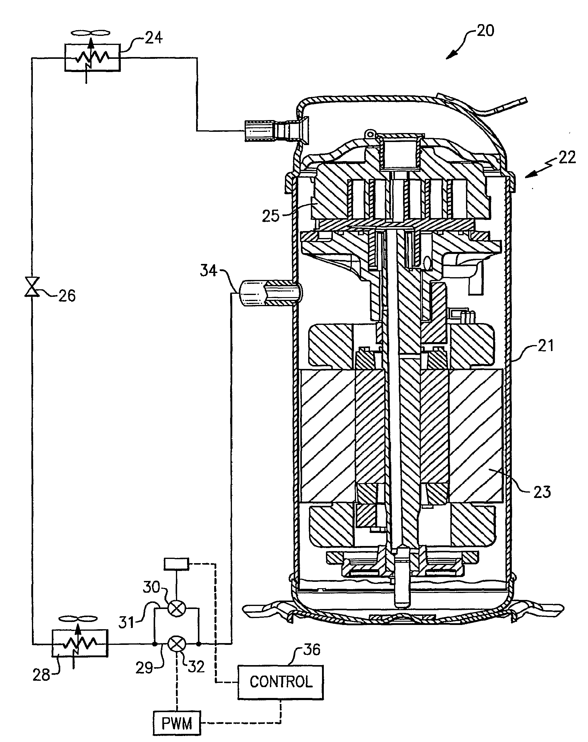
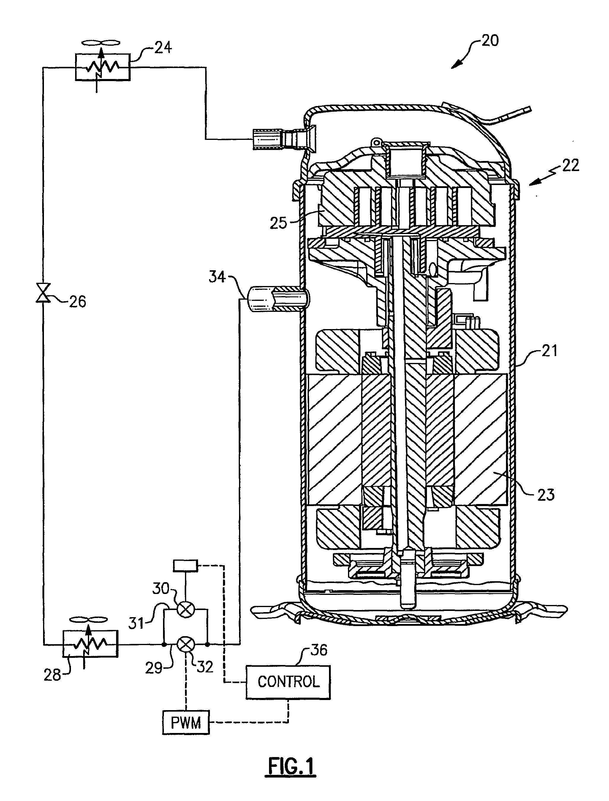
[0011]A refrigerant system 20 is illustrated in FIG. 1 having a sealed compressor 22. As is known, an electric motor 23 drives a compressor pump unit 25 to compress a refrigerant. As is mentioned above, the electric motor 23 can experience harmful “corona discharge” effects should the suction pressure within the shell 21 of the compressor 22 decrease to an unacceptably low level.

[0012]The refrigerant compressed by the compressor 22 passes downstream to a heat exchanger 24, which is typically operating as a condenser. Refrigerant having passed through the heat exchanger 24 passes downstream to an expansion device 26, and then to another heat exchanger 28, which is typically operating as an evaporator.

[0013]Downstream of the evaporator 28, the refrigerant branches into a main flow line 29 and an auxiliary flow branch line 31. The main flow line 29 passes through a pulse width modulation controlled valve 32, and returns to a suction inlet 34 of the compressor 22. Refrigerant, passing t...


PUM


Abstract

A refrigerant system is provided with a pulse width modulation suction valve and a second valve on a line that bypasses the pulse width modulation suction valve. This second valve has a variable opening. In this manner, the pressure within the compressor shell is maintained at the lowest possible level regardless of the system operating conditions, when the pulse width modulation suction valve is cycled to a closed position. Further, the second valve can continue providing capacity control, should the pulse width modulation suction valve fail.

Description

BACKGROUND OF THE INVENTION[0001]This application relates to a refrigerant system wherein a pulse width modulation controlled suction valve is provided, along with an additional refrigerant flow path and a suction modulation valve. The suction modulation valve can be opened to a small degree such that when the pulse width modulation valve is closed, some refrigerant still can leak through to the suction modulation valve and avoid a potentially harmful situation in the compressor due to very low suction pressure.[0002]Refrigerant systems are known, and are utilized to condition a secondary fluid. As an example, an air conditioning system cools and typically dehumidifies air being delivered into a climate controlled environment.[0003]Refrigerant systems generally include a compressor compressing refrigerant and delivering that refrigerant through a discharge line to a downstream heat exchanger. From this downstream heat exchanger, refrigerant passes through an expansion device and the...

Claims


Application Information

Patent Timeline
Patent Type & Authority Applications(United States)
IPC IPC(8): F25B1/00F04B35/04F16K31/02G05D7/00
CPCB60H1/00428F25B2600/2521F25B41/043B60H1/3223F25B41/22
Inventor LIFSON, ALEXANDERTARAS, MICHAEL F.
Owner CARRIER CORP
Why Eureka
Try Eureka