Engine-driven air source heat pump

An air-source heat pump and engine-driven technology, which is applied to refrigerators, compressors, compressors, etc., to achieve the effects of reducing energy consumption, reducing gas resistance, and reducing unit costs

Active Publication Date: 2022-01-07
SHANGHAI AIRUTE AIR CONDITIONING SYST
View PDF8 Cites 3 Cited by
  • Summary
  • Abstract
  • Description
  • Claims
  • Application Information

AI Technical Summary

Problems solved by technology

In this patent, in areas with high air humidity, the waste heat of flue gas and cylinder jacket water cannot be used to share the heat exchange of air source heat exchangers to achieve frost-free operation.

Method used


Image

  • Engine-driven air source heat pump
  • Engine-driven air source heat pump
  • Engine-driven air source heat pump

Examples


Embodiment 1

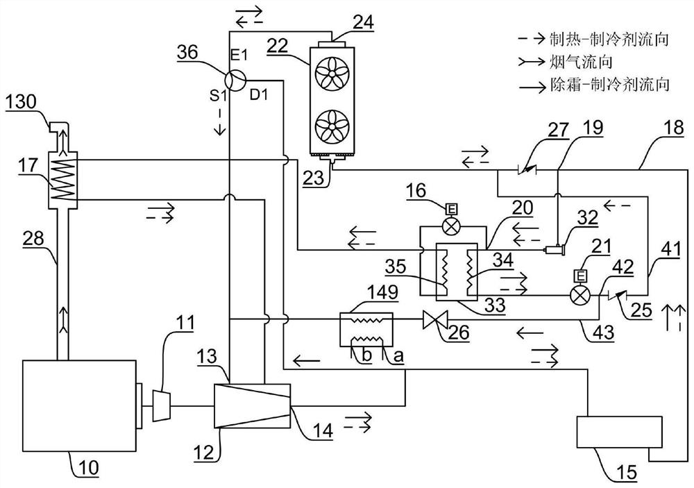
[0035] This embodiment provides an engine-driven air source heat pump. figure 1 It is a schematic diagram of the connection and flow chart of the main part of the engine-driven air source heat pump in Embodiment 1 of the present invention; figure 2 It is a schematic diagram of the connection and flow of the peripheral parts of the engine-driven air source heat pump in Embodiment 1 of the present invention.

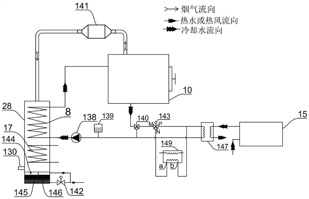
[0036] Such as figure 1 and figure 2 As shown, the engine driven air source heat pump includes a main body portion and a peripheral portion. Among them, the main part includes engine 10, transmission device 11, compressor 12, first heat exchanger 15, first throttle valve 16, flue gas refrigerant heat exchanger 17, first pipeline 18, second throttle valve 21. The second heat exchanger 22 , the first switching valve 25 , the second switching valve 26 , the economizer 33 , the refrigerant three-way valve 36 , and the cooling water refrigerant heat exchanger 149 . The pe...

Embodiment 2

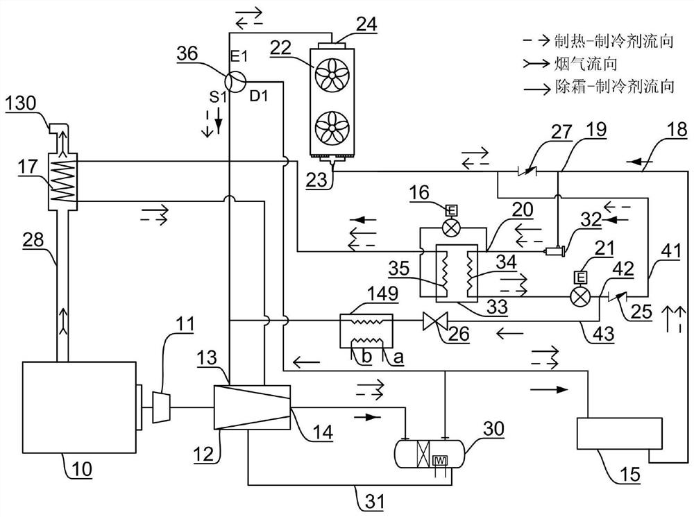
[0061] image 3 It is a schematic diagram of the connection and flow chart of the main part of the engine-driven air source heat pump in the second embodiment of the present invention.

[0062] Such as image 3 As shown, Embodiment 2 provides an engine-driven engine-driven air-source heat pump. The difference between the engine-driven air-source heat pump and Embodiment 1 is that the main part of the engine-driven air-source heat pump in this embodiment also includes an oil separator 30, lubricating oil circuit 31, dry filter 32. The first heat exchanger 15 of this embodiment does not include the oil separator 30 .

[0063] The other structures in this embodiment are the same as in Embodiment 1, and the same numbers are assigned to the same structures.

[0064] image 3 Among them, the oil separator 30 has an oil-separated refrigerant inlet, an oil-separated refrigerant outlet, and a lubricating oil discharge port, the oil-separated refrigerant inlet communicates with the ...

Embodiment 3

[0074] Figure 4 It is a schematic diagram of the connection and flow chart of the main part of the engine-driven air source heat pump in Embodiment 3 of the present invention.

[0075] Such as Figure 4 As shown, Embodiment 3 provides an engine-driven engine-driven air source heat pump. The difference between the engine-driven air source heat pump and Embodiment 1 is that the main part of the engine-driven air source heat pump in this embodiment also includes a fourth switch valve 38 , third heat exchanger 39 , and fifth switching valve 40 .

[0076] The other structures in this embodiment are the same as in Embodiment 1, and the same numbers are assigned to the same structures.

[0077] Figure 4 Among them, the first communication port 23 is connected to the second connection point 20 through the fourth switching valve 38 and the second throttle valve 21 , and the fourth switching valve 38 is closer to the first communication port 23 than the second throttle valve 21 . ...


PUM


Abstract

The invention provides an engine-driven air source heat pump which is used for producing hot water or hot air. The engine-driven air source heat pump comprises an engine, a transmission device, a compressor, a first heat exchanger, a second heat exchanger and an economizer, the compressor is provided with an exhaust port, an air suction port and an air supply port, and the second heat exchanger is provided with a first circulation port and a second circulation port. The engine-driven air source heat pump is characterized by further comprising a smoke refrigerant heat exchanger, a cooling water refrigerant heat exchanger and a refrigerant three-way valve, wherein refrigerant in the smoke refrigerant heat exchanger absorbs heat and evaporates from smoke in a smoke exhaust pipeline of the engine, the smoke refrigerant heat exchanger is connected with refrigerant of the economizer in series or in parallel, the refrigerant absorbs heat and evaporates in the smoke refrigerant heat exchanger and the economizer and then returns to the compressor through the air supply port, refrigerant in the cooling water refrigerant heat exchanger absorbs heat and evaporates in cooling water and communicates with the air suction port, and the second circulation port is connected with the exhaust port and the air suction port through the first refrigerant three-way valve.

Description

technical field [0001] The invention belongs to the technical field of heat pumps, and in particular relates to an engine-driven air source heat pump. Background technique [0002] At present, boilers widely used consume a lot of primary energy, have high operating costs, and generate a large amount of carbon emissions. Engine-driven air source heat pumps have the characteristics of high efficiency, low operating costs, and low carbon emissions. With the implementation of sustainable development strategies and the continuous strengthening of energy conservation and environmental protection awareness, high-efficiency engines that use biomass or solar synthetic fuels to drive air The efficiency of the source heat pump is more than 1 times higher than that of the boiler. Independent heating does not have the phenomenon of cogeneration of heat and power in winter. It is an inevitable choice to replace the boiler or cogeneration. The engine-driven air source heat pump has signif...

Claims


Application Information

Patent Timeline
Patent Type & Authority Applications(China)
IPC IPC(8): F25B13/00F25B27/02F25B31/00F25B41/20F25B43/02F25B47/02F25B49/02
CPCF25B13/00F25B27/02F25B31/004F25B41/20F25B43/02F25B47/02F25B49/02F25B2327/001F25B2347/02Y02A30/274
Inventor 张小力
Owner SHANGHAI AIRUTE AIR CONDITIONING SYST
Why Eureka
Try Eureka