

Sun tracing device
a tracing device and sun technology, applied in the field of sun tracing devices, can solve the problems of easy restriction of solar energy for its own properties, and achieve the effect of accurately aiming at the sun, saving energy, and high energy
- Summary
- Abstract
- Description
- Claims
- Application Information
AI Technical Summary
Benefits of technology
Problems solved by technology
Method used
Image

Examples
Embodiment Construction
[0019]The present invention will be apparent from the following detailed description, which proceeds with reference to the accompanying drawings, wherein the same references relate to the same elements.
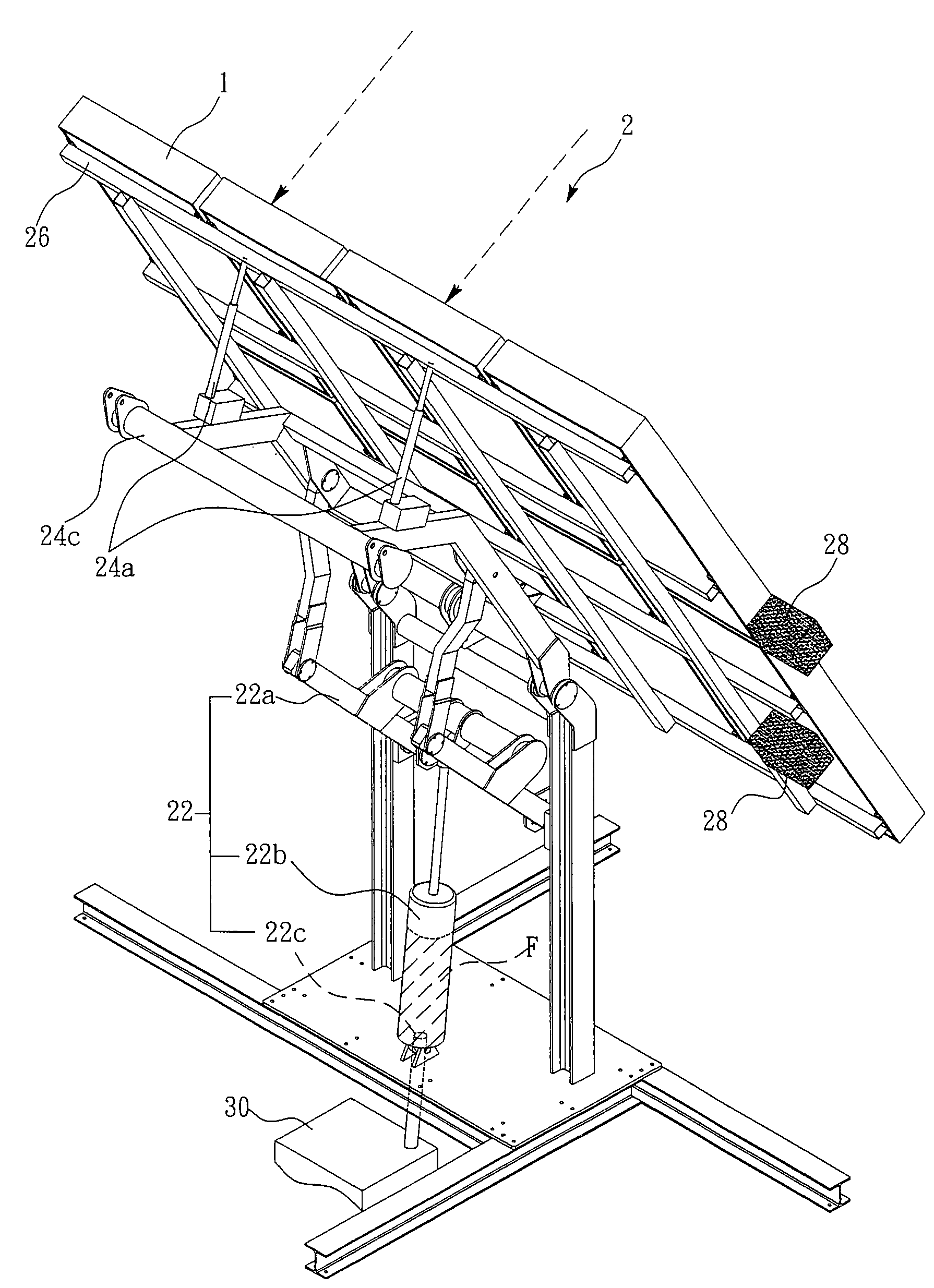
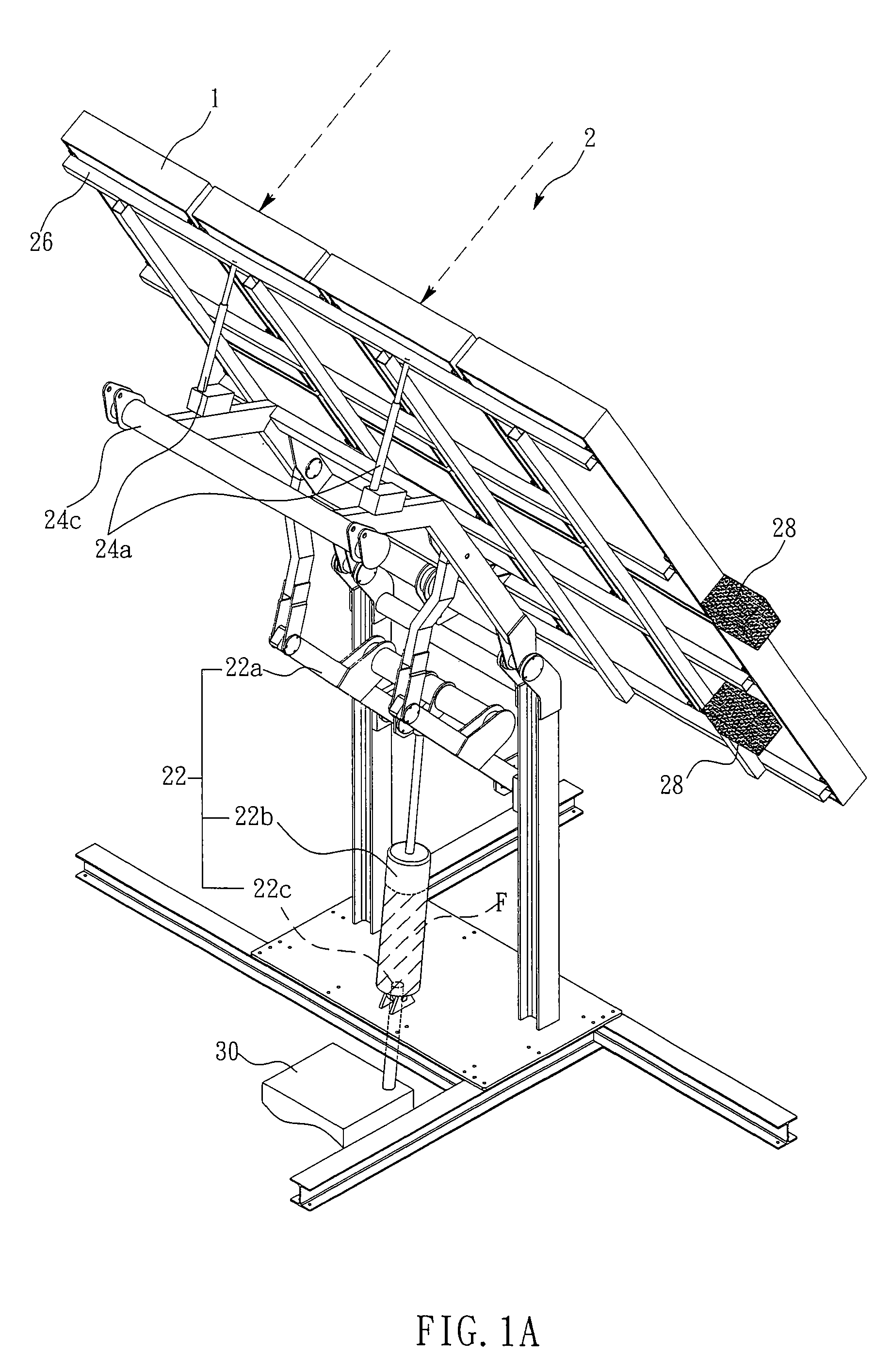
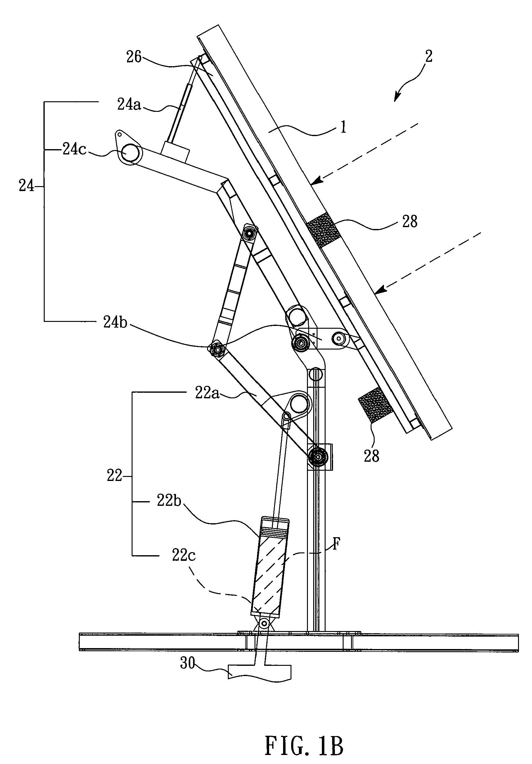
[0020]FIGS. 1A and 1B are schematic views of an initial structure of a sun tracing device 2 in the different view angles. FIGS. 2A and 2B are schematic views of a using structure of a sun tracing device 2 in the different view angles. FIGS. 3A and 3B are schematic views of a final structure of a sun tracing device 2 in the different view angles. With reference to FIGS. 1A, 1B, 2A, 2B, 3A, and 3B, these figures respectively disclose the structural schematic views of an initial state (e.g. at sunrise), a using state (e.g. in the noon), and a final state (e.g. in the evening) of a sun tracing device (carrying a photoelectric transformation unit 1) in the different view angles. The sun tracing device 2 that includes a power unit 22, a supporting plate 26, and an adjusting unit 24 further ...
PUM
 Abstract
Description
Claims
Application Information