Self Propelled Electric Vehicle Recharging Trailer

a self-propelled electric vehicle and charging trailer technology, applied in the direction of electric devices, propulsion parts, process and machine control, etc., can solve the problems of over-four hours of full recharge even at a 40 amp 220 volt class two charging station

Inactive Publication Date: 2010-03-18
COLLINGS III JOHN K
View PDF24 Cites 199 Cited by
  • Summary
  • Abstract
  • Description
  • Claims
  • Application Information

AI Technical Summary

Problems solved by technology

Other than cost, electric vehicles have not achieved the utility of gasoline or diesel powered vehicles for of two important reasons: (1) the power density of current and expected battery technology is far less than gasoline or diesel fuel; and (2) the automobile market is extensively served by ubiquitous fueling stations where, in about ten minutes, approximately 400 miles of travel fuel can be obtained.
While the result provides great utility it also provides substantial compromises in the vehicles electric only range and increase in price.
But a full recharge even at a 40 amp 220 volt class two charging station takes over four hours.
Therefore the vehicle has little utility for any non-commuter travel, even though for the majority of vehicles this kind of travel makes up a small portion of the vehicles total miles driven.
This substantially reduces the vehicles general appeal.
While this solution works, it presents cost, safety, utility and performance problems.
The core issue is that all of the motor, drive train and suspension systems must be built to accommodate the weight of the temporary combustion power system or else the combined vehicle suffers substantial performance and maintenance issues.
But then the solution is back to one with a reduced the electric only range and a third more cost.
The electric vehicle owner has no way of accurately accounting for the charging during the day or when away from home.
The problem is that for real acceptance of the electric vehicle (and the subsequent mass appeal and deployment of electric vehicles) there must be real convenience in using the vehicle and that means a vastly greater number of electric charging stations then there are electric vehicles to ensure the vehicle owner they can go where they want.
It is a “chicken or the egg” deployment problem.
The cost of deploying many times more dedicated electric meters, circuits and transaction equipment than there are electric vehicles is potentially an issue that can substantially restrain the growth of the electric vehicle market, and the great societal benefits that accompany that industries emergence.
While this works, combustions engines cost two to four times as much as a motive force when compared to electricity.
Currently the electric vehicle industry is anticipating un-metered, or “for hire” charging stations to supply electricity to the fleet.
The primary issue associated with the un-metered charging sites is that while the fleet is small the monetary affect of the vehicle charging on random or consistent host charging sites not operated by the vehicle driver is inconsequential.
One of the major issues with the “for hire” charging stations is their installation.
These requirements can lead to a current cost of approximately $1,000 per charging point.
The work place will not want to offer free charging due to the expense.
This dilemma will reduce the usability of electric vehicles.
The higher installation and operational cost of the currently proposed “for hire” systems will force host providers to charge more for the system than the vehicle / driver based system.
While plausible, this method would result in delays of revenue not currently experienced by government agencies and, more seriously, a large annual bill for the vehicle owner that might well be too high to immediately pay.
Without a smart vehicle system with reporting the home charging issue isn't addressed.

Method used


Image

  • Self Propelled Electric Vehicle Recharging Trailer
  • Self Propelled Electric Vehicle Recharging Trailer
  • Self Propelled Electric Vehicle Recharging Trailer

Examples


Embodiment Construction

[0037]A preferred embodiment of the invention is now described in detail. Referring to the drawings, like numbers indicate like parts throughout the views. Unless otherwise specifically indicated in the disclosure that follows, the drawings are not necessarily drawn to scale. As used in the description herein and throughout the claims, the following terms take the meanings explicitly associated herein, unless the context clearly dictates otherwise: the meaning of “a”, “an,” and “the” includes plural reference, the meaning of “in” includes “in” and “on.”

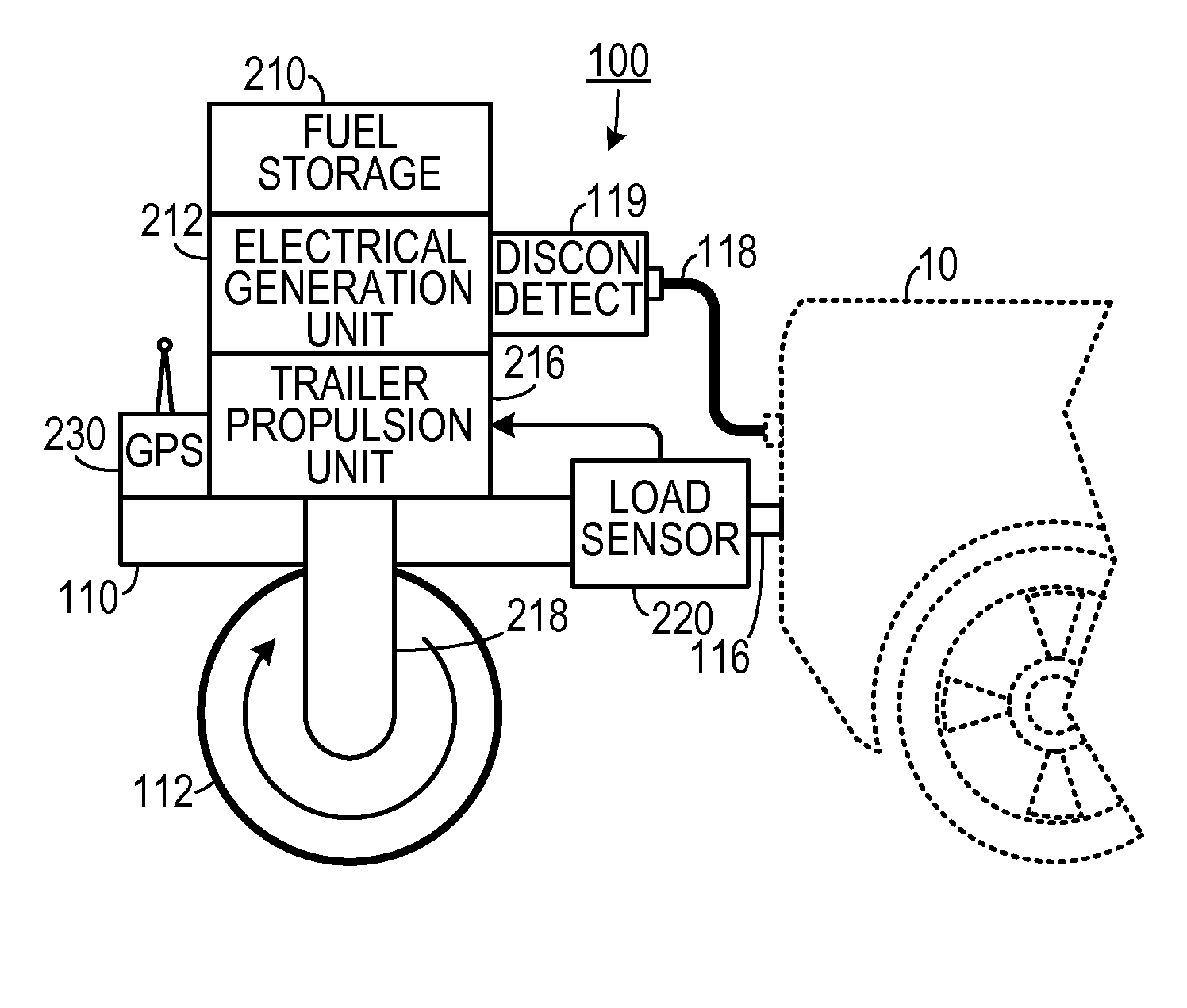
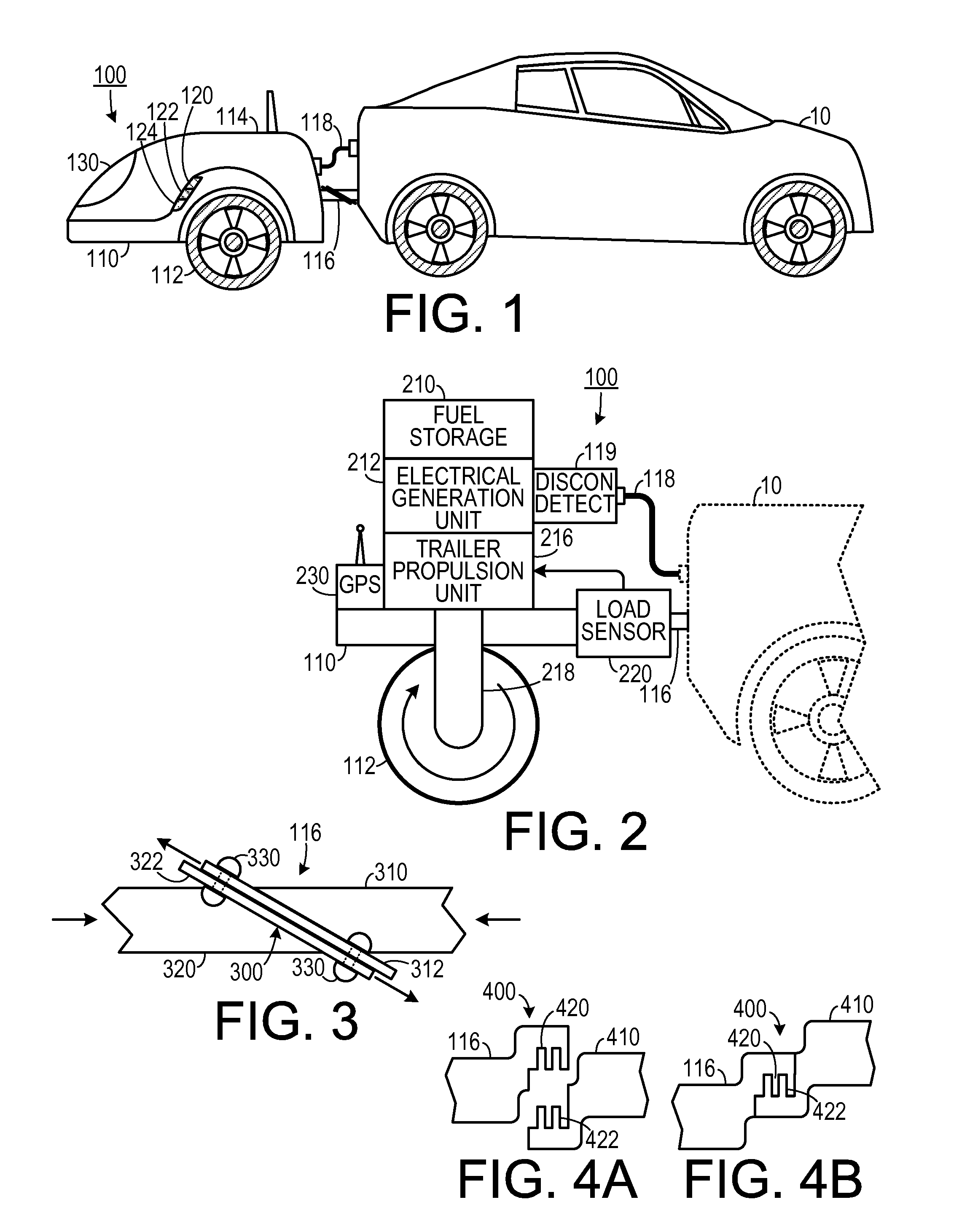
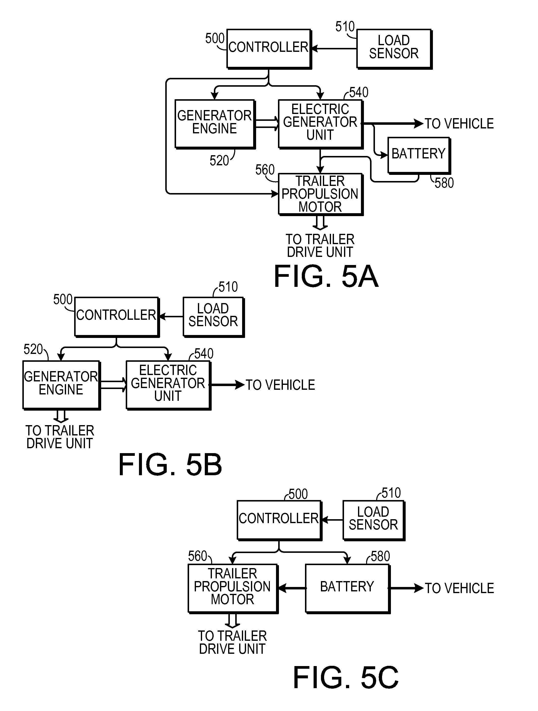
[0038]In one embodiment, the self propelled trailer has sensors that determine the turning, acceleration and deceleration load the trailer is presenting to the host vehicle. Onboard microprocessors and controllers instantly adjust the trailers motive drive to minimize or eliminate the trailers load to the host vehicle, thus improving the general performance of the combined vehicle. Additionally, if the host is an electric vehicle and ...


PUM


Abstract

A recharging trailer for applying electrical energy to an electric vehicle has an electrical power coupling. The recharging trailer includes a trailer frame configured to be coupled to the electronic vehicle. An electrical generation unit is disposed on the trailer and is configured generate electrical power. The electrical generation unit is also configured to be electrically coupled to the electrical power coupling of the electric vehicle. A trailer propulsion unit is configured to propel the trailer while the electrical vehicle is moving so that the trailer moves without applying a substantial load to the electric vehicle.

Description

CROSS-REFERENCE TO RELATED APPLICATION(S)[0001]This application claims the benefit of U.S. Provisional Patent Application Ser. No. 61 / 096,421, filed Sep. 12, 2008, the entirety of which is hereby incorporated herein by reference.BACKGROUND OF THE INVENTION[0002]1. Field of the Invention[0003]The present invention relates to support systems for electric vehicles and, more specifically, to a trailer configured to provide electrical power to an electric vehicle.[0004]2. Description of the Prior Art[0005]Other than cost, electric vehicles have not achieved the utility of gasoline or diesel powered vehicles for of two important reasons: (1) the power density of current and expected battery technology is far less than gasoline or diesel fuel; and (2) the automobile market is extensively served by ubiquitous fueling stations where, in about ten minutes, approximately 400 miles of travel fuel can be obtained. Yet in absolute local energy terms electric vehicles are about five times more eff...

Claims


Application Information

Patent Timeline
Patent Type & Authority Applications(United States)
IPC IPC(8): B60L9/00B62M7/14B60T7/12
CPCB60K6/20B60L1/006B60L11/126B60L11/185B60L2200/28B60L2240/423B60L2270/34B60W10/06B60W10/08B60W10/26B60W20/00B60W2510/244B60W2520/10B60W2520/105B60W2520/28B60W2530/14B60W2710/083B60W2720/30Y02T10/6217Y02T10/6269Y02T10/6286Y02T10/642Y02T10/7005Y02T10/7077Y02T90/128Y02T90/14Y02T90/121B60L11/007B60K6/46B60L3/10B60L50/20B60L50/62B60L53/11B60W2556/10Y02T10/62Y02T10/64Y02T10/70Y02T10/7072B60K6/28B60W2300/145B60W2510/242Y02T90/12
Inventor COLLINGS, III, JOHN K.
Owner COLLINGS III JOHN K
Why Eureka
Try Eureka