Power supply system and vehicle including the same, and method of controlling the same

a technology of power supply system and vehicle, applied in the direction of propulsion parts, propulsion using engine-driven generators, electric devices, etc., can solve the problem that the whole system should inevitably be stopped

Inactive Publication Date: 2010-03-18
TOYOTA JIDOSHA KK
View PDF5 Cites 54 Cited by
  • Summary
  • Abstract
  • Description
  • Claims
  • Application Information

AI Technical Summary

Benefits of technology

[0013]Further preferably, the control unit stops an electric power conversion operation between the first electric power line pair and the corresponding power storage unit and thereafter sets an electrically conducting state therebetween, for each of the plurality of voltage conversion units.
[0014]Further preferably, each of the plurality of voltage conversion units includes a switching element connected in series to an inductor and arranged between one electric power line out of the first electric power line pair and one electrode of the corresponding power storage unit, capable of electrically connecting and disconnecting one electric power line and one electrode of the corresponding power storage unit to / from each other, and a line for electrically connecting another electric power line out of the first electric power line pair and another electrode of the corresponding power storage unit to each other. The control unit maintains a conducting state by setting the switching element to an ON state, for each of the plurality of voltage conversion units.
[0015]In addition, preferably, the control unit controls the remaining voltage conversion unit except for the first voltage conversion unit such that electric power from the corresponding power storage unit is supplied to the first electric power line pair after it is boosted, and controls the first voltage conversion unit such that electric power from the first electric power line pair is supplied to the second load device after it is down-converted.
[0016]Further preferably, the control unit controls the first voltage conversion unit in accordance with a first control mode for attaining a value of a down-converted voltage supplied to the second load device to a prescribed target value.
[0017]Further preferably, the control unit controls at least one of the remaining voltage conversion units in accordance with a second control mode for attaining a value of a boosted voltage supplied to the first electric power line pair to a prescribed target value.
[0018]Further preferably, while the first voltage conversion unit and the corresponding power storage unit are electrically connected to each other, the first voltage conversion unit is set to the second control mode to perform a voltage conversion operation, and each remaining voltage conversion unit is set to a third control mode for attaining a value of electric power supplied and received between the first electric power line pair and the corresponding power storage unit to a prescribed target value to perform a voltage conversion operation. The control unit switches between the control modes for at least one of the remaining voltage conversion units and the first voltage conversion unit in response to electrical disconnection between the first voltage conversion unit and the corresponding power storage unit by the corresponding disconnection unit.

Problems solved by technology

Therefore, if only one of a plurality of power storage units is in the fault condition, the entire system should inevitably be stopped.

Method used


Image

  • Power supply system and vehicle including the same, and method of controlling the same
  • Power supply system and vehicle including the same, and method of controlling the same
  • Power supply system and vehicle including the same, and method of controlling the same

Examples


first embodiment

Configuration of Vehicle

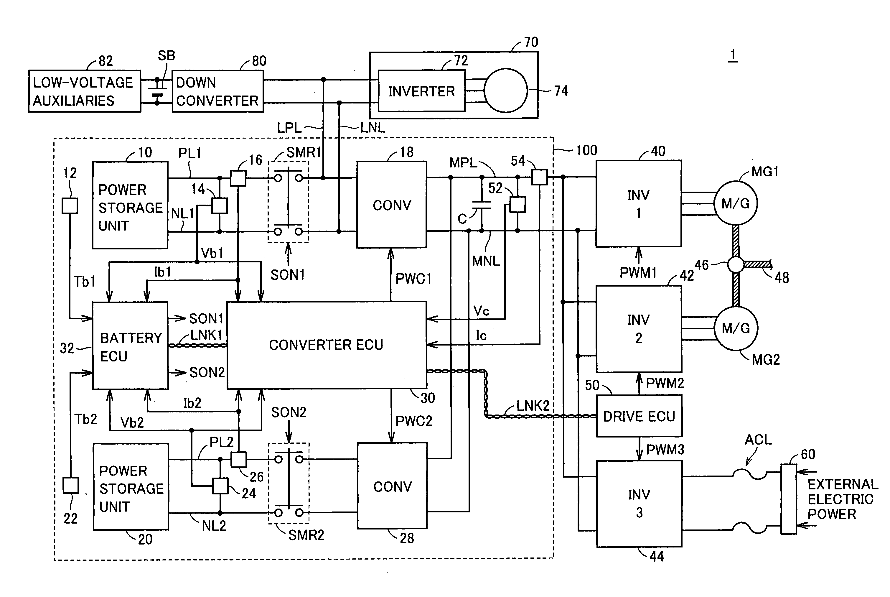
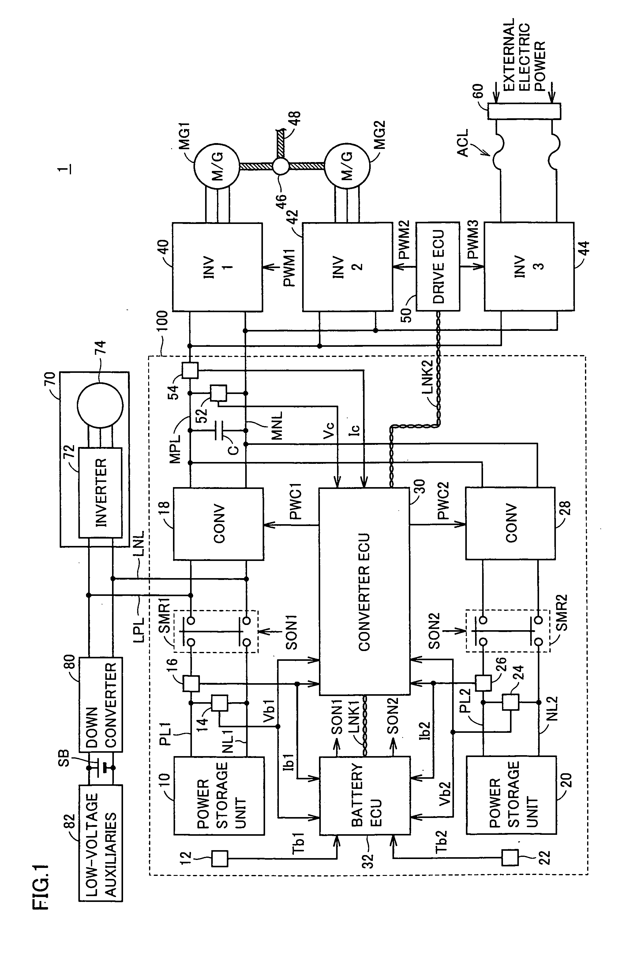
[0043]FIG. 1 is a schematic configuration diagram showing a substantial part of a vehicle 1 including a power supply system 100 according to a first embodiment of the present invention.

[0044]Referring to FIG. 1, vehicle 1 includes power supply system 100, a first inverter (INV1) 40, a second inverter (INV2) 42, a third inverter (INV3) 44, motor-generators (M / G) MG1, MG2, a drive ECU (Electronic Control Unit) 50, an air-conditioning apparatus 70, low-voltage auxiliaries 82, a down converter 80, and a sub power storage unit SB.

[0045]In the present first embodiment, power supply system 1 including two power storage units 10, 20 will be described by way of example of the power supply system including a plurality of power storage units.

[0046]Inverters 40, 42, motor-generators MG1, MG2, and drive ECU 50 constitute a “drive force generation unit” for generating drive force for running vehicle 1. The “drive force generation unit” herein is illustrated as a “first loa...

second embodiment

[0196]In the first embodiment described above, when power storage unit 10 is disconnected from power supply system 100, electric power having a voltage substantially equal to voltage value Vb2 of power storage unit 20 is supplied to the drive force generation unit. Meanwhile, in order to be able to supply electric power having a higher voltage, the voltage conversion operation in converters 18 and 28 may positively be performed.

[0197]As the overall configuration of a power supply system according to the second embodiment of the present invention is the same as power supply system 100 according to the present first embodiment shown in FIG. 1, detailed description will not be repeated. Referring again to FIGS. 3B and 4B, in the present second embodiment, if some kind of fault condition occurs in power storage unit 10 and power storage unit 10 is electrically disconnected from power supply system 100, converter 28 is switched to the “voltage control mode (boost)” and converter 18 is sw...


PUM


Abstract

When power storage units (10) and (20) are both in a normal condition, system relays (SMR1) and (SMR2) are maintained in an ON state. A converter (18) performs a voltage conversion operation in accordance with a voltage control mode (boost), and a converter (28) performs a boost operation in accordance with an electric power control mode. If some kind of fault condition occurs in the power storage unit (10) and the system relay (SMR1) is driven to an OFF state, the converters (18) and (28) stop the voltage conversion operation and maintain an electrically conducting state between the power storage units (10) and (20) and a main positive bus (MPL), a main negative bus (MNL).

Description

TECHNICAL FIELD[0001]The present invention relates to a power supply system having a plurality of power storage units and a vehicle including the same, and a method of controlling the same, and particularly to a control technique in a case where a power storage unit is disconnected from the power supply system.BACKGROUND ART[0002]Recently, considering environmental issues, a hybrid vehicle that runs based on efficient combination of an engine and a motor has been put into practical use. Such a hybrid vehicle includes a power storage unit that can be charged or discharged and generates drive force by supplying electric power to a motor at the time of start or acceleration while it recovers kinetic energy of the vehicle as electric power during running down a slope or during braking. Therefore, a nickel metal hydride battery, a lithium-ion battery or the like adapted to large input / output electric power and charge / discharge capacity has been adopted as the power storage unit included ...

Claims


Application Information

Patent Timeline
Patent Type & Authority Applications(United States)
IPC IPC(8): B60K1/00H02J1/10B60L50/15B60L50/16
CPCB60K1/02Y02T10/7241B60L3/0046B60L11/123B60L11/14B60L11/1816B60L2210/40B60L2270/20B60W10/08B60W10/26B60W20/00Y02T10/6217Y02T10/6269Y02T10/7005Y02T10/7077Y02T90/127Y02T90/14B60K6/20H02M1/10H02P2201/09B60L3/0092B60L3/04B60L2240/526Y02T10/7072H02J1/102H02J7/34Y02T10/92B60L50/61B60L50/16B60L58/20H02J3/0073H02J1/082B60L53/18B60L58/13B60L58/15Y02T10/62Y02T10/64Y02T10/70Y02T10/72H02M7/48B60K6/28B60K6/26B60K6/445Y02T90/12
Inventor ICHIKAWA, SHINJISATO, EIJI
Owner TOYOTA JIDOSHA KK
Why Eureka
Try Eureka