Method of manufacturing quartz resonator element, quartz resonator element, quartz resonator, and quartz oscillator

a manufacturing method and technology for quartz resonators, applied in the direction of generators/motors, piezoelectric/electrostrictive transducers, transducer types, etc., can solve the problems of frequency characteristic changes before and after heat treatment, metal adhesion to quartz pieces is weak, etc., to increase the manufacturing cost of quartz resonators, increase the electrical resistance of electrodes, and reduce the ci value

Inactive Publication Date: 2010-03-18
NIHON DEMPA KOGYO CO LTD
View PDF13 Cites 17 Cited by
  • Summary
  • Abstract
  • Description
  • Claims
  • Application Information

AI Technical Summary

Benefits of technology

[0023]According to the present invention, a film thickness of the first metal layer before the heat treatment is set to be not less than 20 Å nor more than 45 Å, so that a concentration rise in the chromium to be diffused from the first metal layer into the second metal layer by the heat treatment is suppressed. As a result, an increase in electrical resistance of the electrode constituted by these metal layers is suppressed, and the quartz resonator element having the low CI value comp...

Problems solved by technology

However, the metal has weak adhesion to the quartz piece 11.
Therefore, a desired oscillation frequency cannot be obtained, resulting that there is a problem that frequency adjustment is required again.
Note that arts described in Patent Documents 1 and 2 do not pay attention to a problem that the CI value is increased due to the diffusion of the chromiu...

Method used


Image

  • Method of manufacturing quartz resonator element, quartz resonator element, quartz resonator, and quartz oscillator
  • Method of manufacturing quartz resonator element, quartz resonator element, quartz resonator, and quartz oscillator
  • Method of manufacturing quartz resonator element, quartz resonator element, quartz resonator, and quartz oscillator

Examples


Embodiment Construction

)

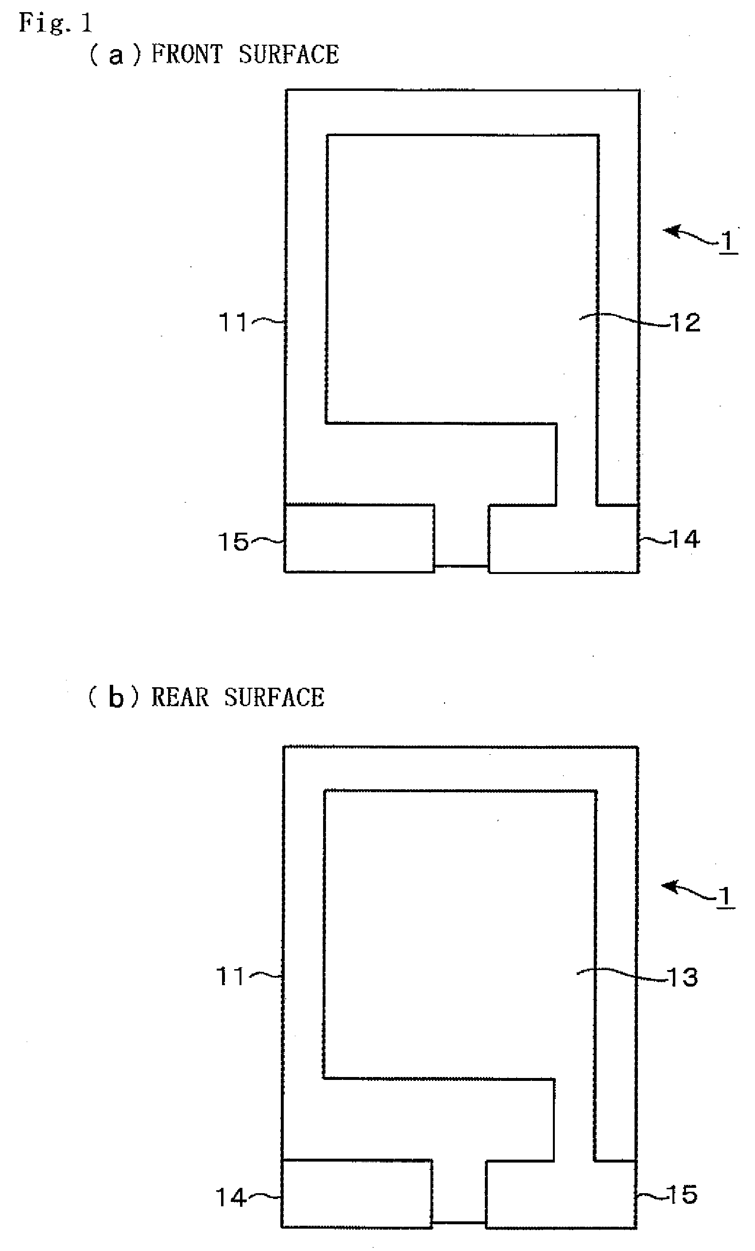
[0029]Hereinafter, a method of manufacturing a quartz resonator element 1 according to the present embodiment and a structure of the quartz resonator element 1 will be explained with reference to FIG. 3 and FIG. 4. The method of manufacturing the quartz resonator element 1 according to the present embodiment has an object to suppress a rise in electrical resistance of each of electrodes 12 to 15 by a heat treatment, and is characterized in that as for a first metal layer composed of chromium and a second metal layer composed of gold or silver, film thicknesses of these thin films in forming the films are adjusted within a predetermined range. Thus, external structures of the quartz resonator element 1 are the same as those explained already by using FIG. 1(a) andFIG. 1(b), and the repeated explanation is omitted. Note that manufacturing processes when gold is used as the second metal layer will be explained below, but manufacturing processes when silver is used as the second metal ...


PUM

PropertyMeasurementUnit
Temperatureaaaaaaaaaa
Thicknessaaaaaaaaaa

Abstract

To provide a method of manufacturing a quartz resonator element having a small CI value, a quartz resonator element manufactured by this method, a quartz resonator, and a quartz oscillator.
In a method of manufacturing a quartz resonator element in which on a surface of a plate-shaped quartz piece, a thin film-shaped electrode in order to excite the quartz piece is provided, a first metal layer that is composed of chromium and whose thickness is not less than 20 Å nor more than 45 Å is formed on the surface of the quartz piece (P4), and next, a second metal layer that is composed of gold or silver and whose thickness is not less than 500 Å nor more than 950 Å is formed on an upper surface of the first metal layer (P5), and then, the electrode made up of the first metal layer and the second metal layer is provided (P6). Thereafter, a quartz substrate on which the electrode is formed is heated at a temperature range of not less than 200° C. nor more than 400° C., and the chromium composing the first metal layer is diffused into the second metal layer (P7).

Description

BACKGROUND OF THE INVENTION[0001]1. Field of the Invention[0002]The present invention relates to a method of manufacturing a quartz resonator element in which on a quartz piece, a thin film-shaped electrode in order to excite the quartz piece is provided, a quartz resonator element, a quartz resonator, and a quartz oscillator.[0003]2. Description of the Related Art[0004]A quartz resonator element is an element constituted by a quartz piece and thin film-shaped electrodes each provided on both surfaces of the quartz piece, and is widely used for an electronic component of a quartz oscillator or the like as a reference source of a frequency or time by using a characteristic in which oscillation is excited by an inverse piezoelectric effect of quartz when a voltage is applied to the electrodes.[0005]As external structures of a front surface side and a rear surface side are illustrated in FIG. 1(a) and FIG. 1(b), a rectangular quartz resonator element 1 using, for example, an AT cut qua...

Claims


Application Information

Patent Timeline
IPC IPC(8): H01L41/047H01L41/22H03H3/02H03H9/10
CPCH03H3/02H03H9/10Y10T29/42H03H9/131H03H9/132H03H9/1021
Inventor TAKAHASHI, TAKEHIRO
Owner NIHON DEMPA KOGYO CO LTD
Why Eureka
Try Eureka