Device for determining the distance between a rotor blade and a wall of a turbine engine surrounding the rotor blade

a technology of turbine engine and rotor blade, which is applied in the direction of machines/engines, liquid fuel engines, instruments, etc., can solve the problems of unnecessarily low efficiency, damage to transmitting and receiving units, and limited spatial resolution and service life of sensors, etc., to achieve good temperature stability of sealing elements, reduce the effect of technical overhead, and reduce the cost of operation

Inactive Publication Date: 2010-03-18
SIEMENS AG
View PDF18 Cites 34 Cited by
  • Summary
  • Abstract
  • Description
  • Claims
  • Application Information

AI Technical Summary

Benefits of technology

[0017]It is therefore possible to perform a distance measurement with the aid of electromagnetic waves which are guided by means of a waveguide through the wall of the turbine engine into the rotor blade region without the extreme conditions prevailing in the rotor blade region penetrating through the waveguide.
[0019]The sealing element can thus be provided in the region of the waveguide opening. In this way an optimal level of protection is ensured for the waveguide and the devices connected to the waveguide, such as e.g. the evaluation unit.
[0020]Advantageously, at least one of the two surfaces can be embodied as convex, thereby enabling the electromagnetic waves having the at least one frequency to be emitted onto the rotor blade in a focused manner. In this way it is possible also to resolve in particular the tip of the rotor blade laterally such that a rotor blade tip profile can be determined.
[0023]It can be of advantage if the sealing element has a dielectric constant ε in the range from 6 to 20, in particular 9 to 15. In this way the optical path of the electromagnetic waves in the waveguide can be influenced by means of the sealing element with little technical overhead being necessary at the sealing element. Moreover, if the sealing element is embodied as a resonator, a sufficiently high reflectivity of the sealing element surfaces (i.e. of the resonator surfaces) is guaranteed.
[0024]It can be favorable in this case if the sealing element is embodied from a ceramic, in particular Al2O3. In this way a very good temperature stability of the sealing element is ensured.

Problems solved by technology

A minimum radial clearance must be satisfied for safety reasons, although too great a radial clearance results in unnecessarily low efficiency.
However, these sensors are limited in terms of accuracy, spatial resolution and service life.
These extreme conditions can penetrate at least so far through the waveguide to the transmit and receive unit connected to the waveguide that said transmit and receive unit will be damaged.

Method used


Image

  • Device for determining the distance between a rotor blade and a wall of a turbine engine surrounding the rotor blade
  • Device for determining the distance between a rotor blade and a wall of a turbine engine surrounding the rotor blade
  • Device for determining the distance between a rotor blade and a wall of a turbine engine surrounding the rotor blade

Examples


Embodiment Construction

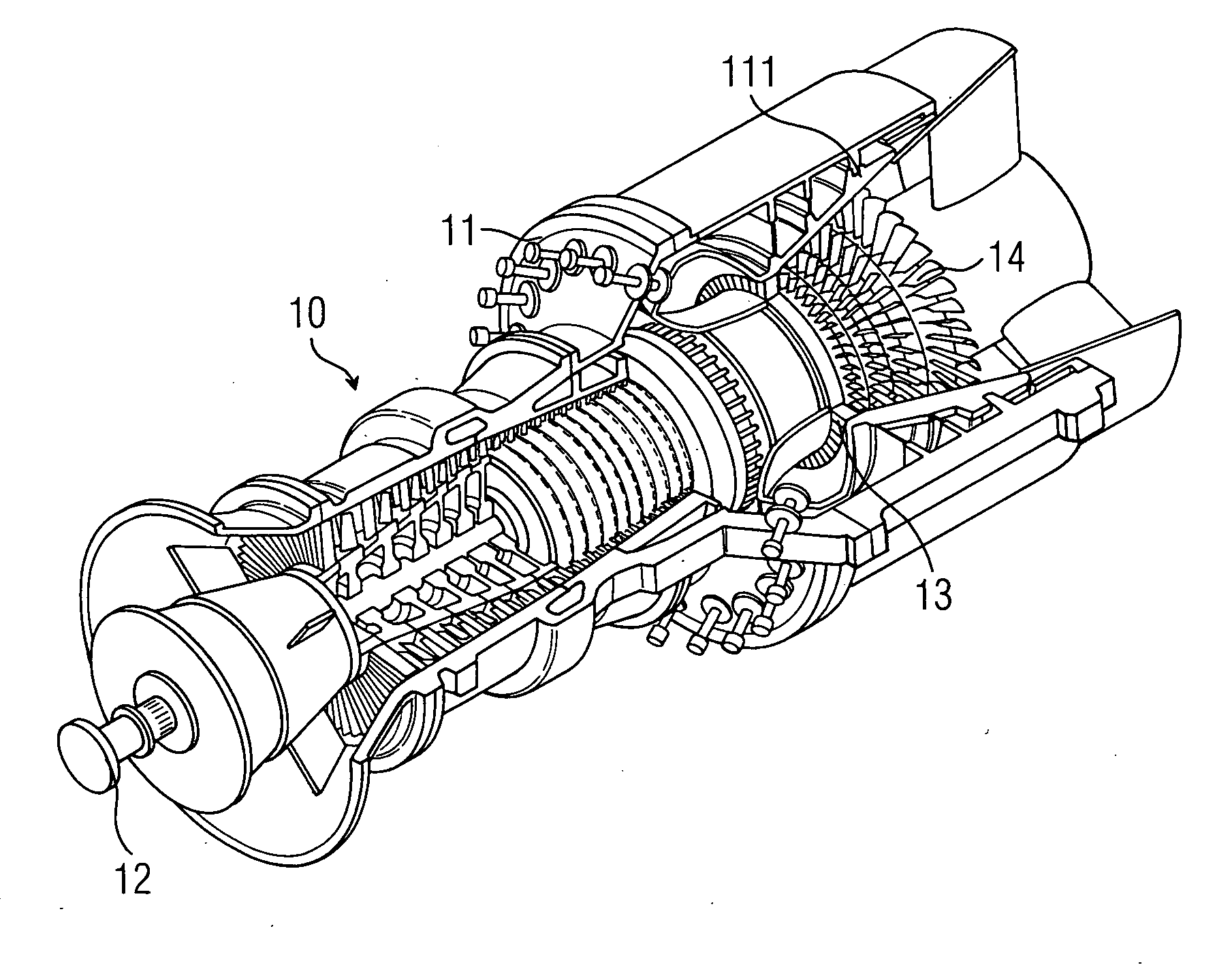
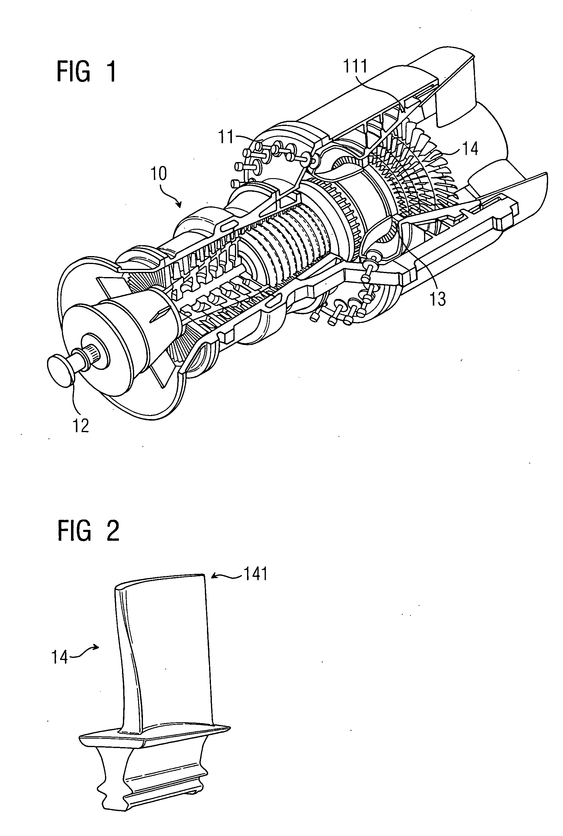
[0035]FIG. 1 shows a gas turbine 10 according to the prior art which is designed for a high gas inlet temperature of approximately 1200° C. In a housing 11 comprising an inner wall 111, the gas turbine 10 has a rotatably mounted rotor shaft 12 on which rotor blades 14 are arranged in a flow channel 13.

[0036]FIG. 2 shows a rotor blade 14 of said type in detail in the uninstalled state. In the installed state the upper end of the rotor blade 14, the so-called rotor blade tip 141, faces the inner wall 111 of the gas turbine housing 11.

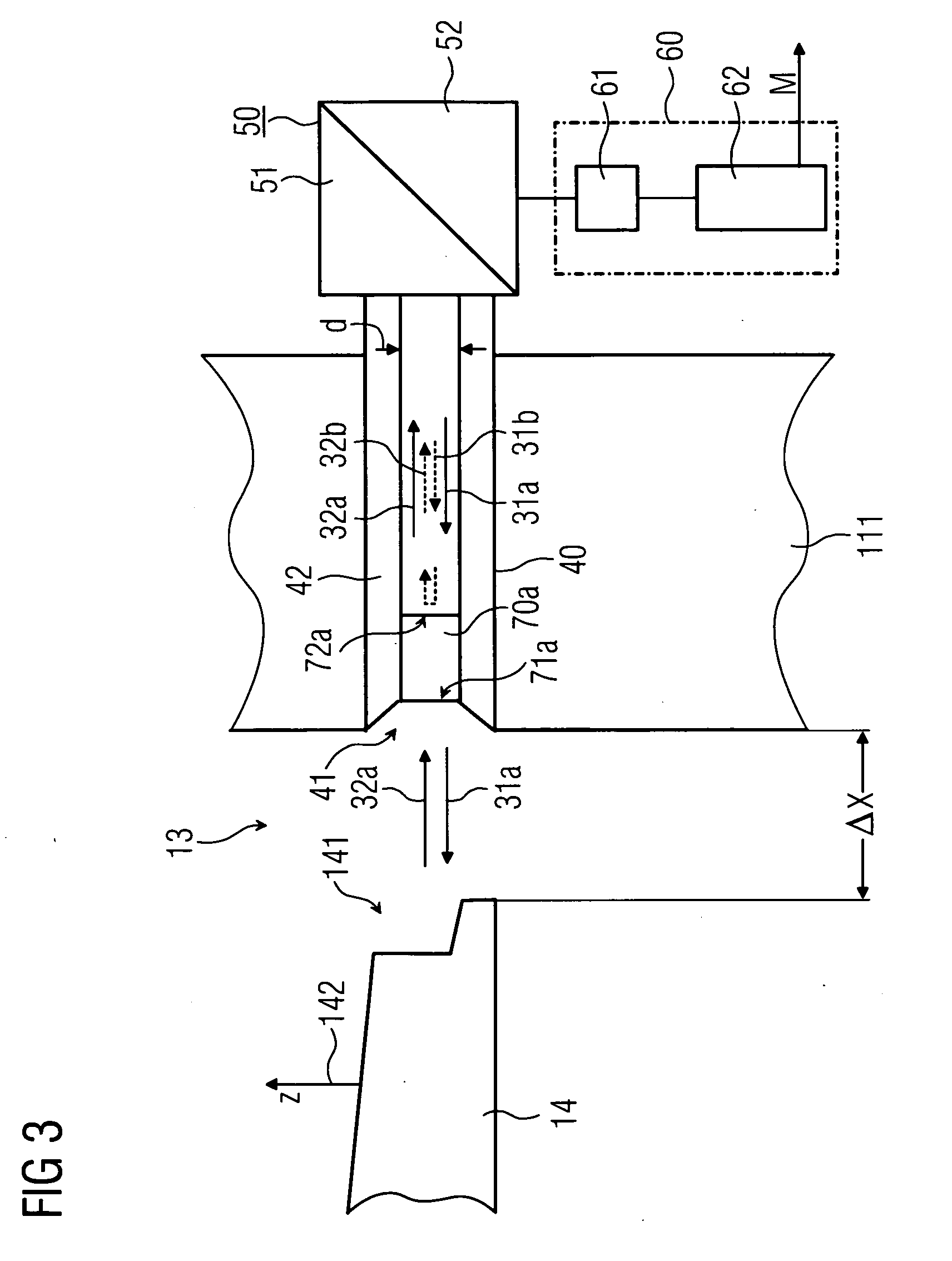
[0037]FIG. 3 shows a schematic illustration of the inventive device in a first exemplary embodiment. For the sake of simplicity, only part of a rotor blade 14 is shown in outline. The arrow 142 indicates that during a distance measurement the rotor blade 14 moves in the direction of the arrow 142 during operation of the gas turbine 10. In a first approximation the movement in the direction of the arrow can be considered as a linear movement in the lateral...


PUM


Abstract

A device for determining distance between a rotor blade and a wall of a gas turbine surrounding the rotor blade is provided. A waveguide guides and emits electromagnetic waves of at least one frequency in the direction of the rotor blade through a waveguide opening facing the rotor blade. The electromagnetic waves are injected into the waveguide and reflected portions of the electromagnetic waves are received. An evaluation unit compares the phase of the electromagnetic waves to be injected with the phase of the reflected portions of the electromagnetic waves and determines phase comparison values for every frequency and the distance is determined based on the phase comparison values. The waveguide comprises a sealing element which is configured to be transmissible for the electromagnetic waves of the frequency and which has two opposite surfaces in the direction of guidance of the electromagnetic waves.

Description

CROSS REFERENCE TO RELATED APPLICATIONS[0001]This application is the US National Stage of International Application No. PCT / EP2007 / 059084, filed Aug. 30, 2007 and claims the benefit thereof. The International Application claims the benefits of German application No. 10 2006 046 696.9 filed Sep. 29, 2006, both of the applications are incorporated by reference herein in their entirety.FIELD OF THE INVENTION[0002]The invention relates to a device for determining the distance between at least one rotor blade and a wall of a turbine engine, said wall surrounding the at least one rotor blade, and to a use of the method.BACKGROUND OF THE INVENTION[0003]Turbine engines such as steam or gas turbines, for example, are utilized as thermal power engines in engineering for the purpose of converting energy which is stored in a flow of gas into a mechanical energy, in particular into a rotational movement. In order to ensure the reliable operation of turbine engines of said kind, efforts are made ...

Claims


Application Information

Patent Timeline
Patent Type & Authority Applications(United States)
IPC IPC(8): G01R27/04G01M99/00
CPCG01B15/00G01B7/14G01B11/14
Inventor BOSSELMANN, THOMASWILLSCH, MICHAEL
Owner SIEMENS AG
Why Eureka
Try Eureka