
Method for measuring location of radio frequency identification reader by using beacon

location technology, applied in the field of method for measuring the location of a radio frequency identification (rfid) reader, can solve the problems of difficult to accurately measure a location, high error rate, and sensitive direction of ultrasonic waves, and achieve the effect of easy and accurate measuremen

Active Publication Date: 2010-03-18
SK TELECOM CO LTD +1
View PDF5 Cites 42 Cited by
  • Summary
  • Abstract
  • Description
  • Claims
  • Application Information

AI Technical Summary

Benefits of technology

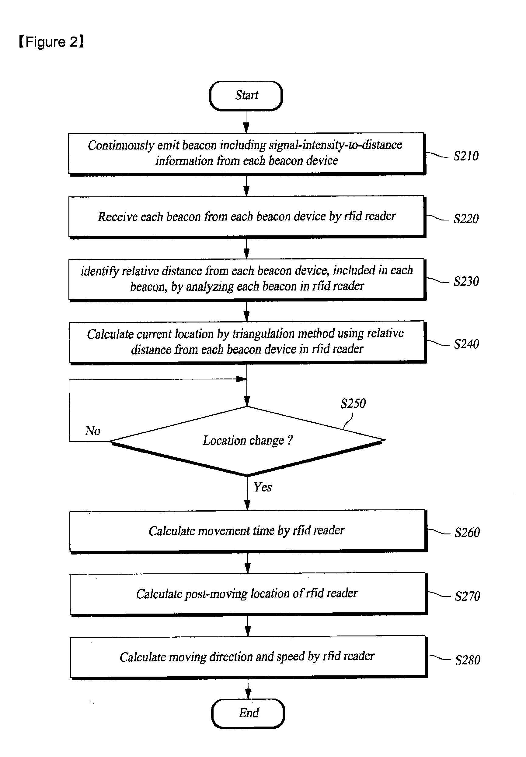
[0009]Therefore, the present invention has been made in view of the above-mentioned problems, and it is an object of the present invention to provide a location measurement method for easily and accurately measuring a location of a moving radio frequency identification (RFID) reader in an RFID system, and the same RFID system, in such a manner that the RFID system includes a plurality of beacon devices, which are fixed at predetermined locations and emit beacons including reference location information about their own reference locations and signal-intensity-to-distance information, and that the RFID reader receives beacons from at least three beacon devices, identifies relative distances from the respective beacon devices by using signal-intensity-to-distance information included in the beacons, and calculates its own location through a triangulation method.

Problems solved by technology

In the case of using the RSSI, since the characteristics of the RF signals vary depending on the environments, there are defects in that it is difficult to accurately measure a location, and that an error rate is high.
In the case of using the ultrasonic waves, there are defects in that the ultrasonic waves are sensitive to directions due to the characteristics of sound waves, and that equipment is heavy.

Method used


Image

  • Method for measuring location of radio frequency identification reader by using beacon
  • Method for measuring location of radio frequency identification reader by using beacon
  • Method for measuring location of radio frequency identification reader by using beacon

Examples


Embodiment Construction

[0017]Hereinafter, preferred embodiments of the present invention will be described with reference to the accompanying drawings. First, it is to be noted that the same elements are indicated with the same reference numerals throughout the drawings. In the following description, a detailed description of known functions and configurations incorporated herein will be omitted when it may make the subject matter of the present invention rather unclear.

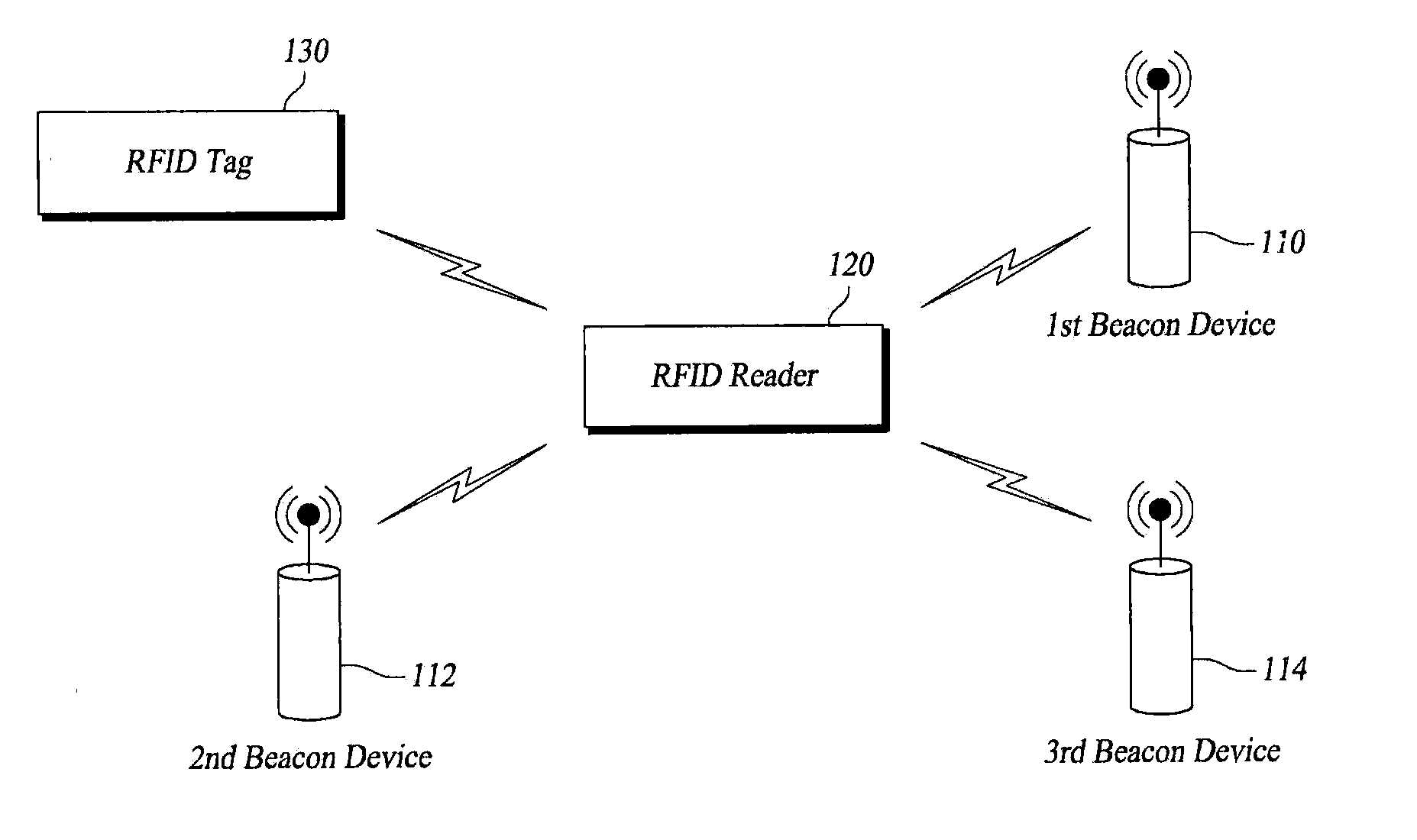
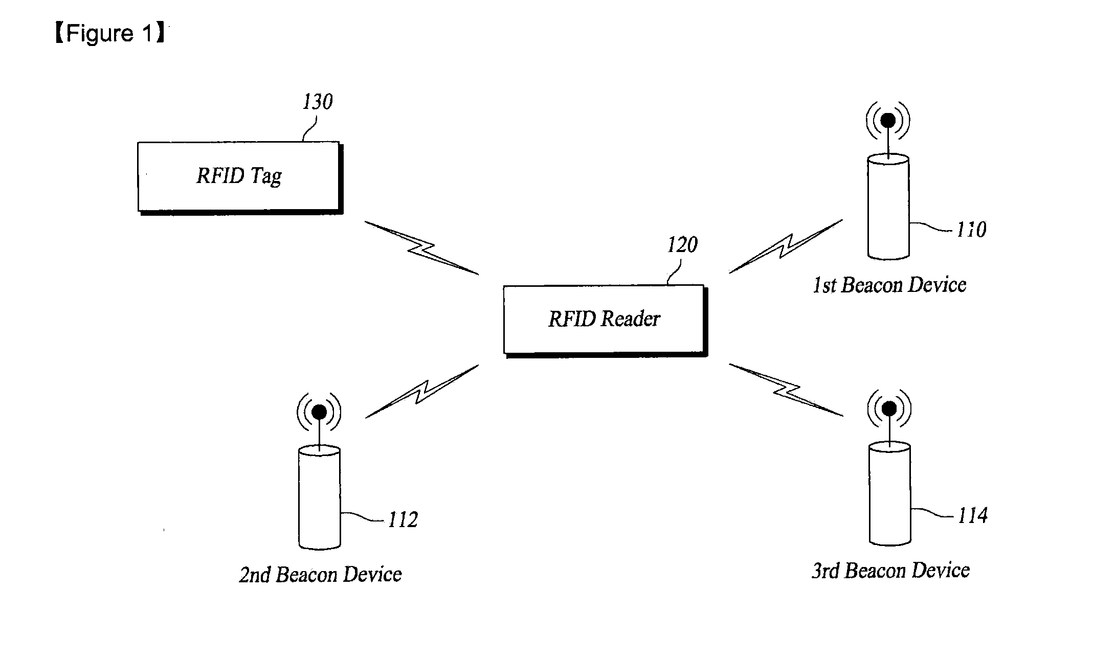
[0018]FIG. 1 is a block diagram schematically illustrating the configuration of a radio frequency identification (RFID) system for measuring the location of an RFID reader by using beacons according to an exemplary embodiment of the present invention.

[0019]According to an exemplary embodiment of the present invention, the RFID system for measuring the location of an RFID reader by using beacons includes a first beacon device 110, a second beacon device 112, a third beacon device 114, an RFID reader 120, and an RFID tag 130.

[0020]The first ...


PUM


Abstract

The present invention relates to a method for measuring a location of a radio frequency identification (RFID) reader by using beacons, and an RFID system for measuring a location of a moving RFID reader in an RFID system comprising: a plurality of beacon devices for emitting beacons; an RFID tag for transmitting pre-stored information by using radio frequency identification; and an RFID reader for calculating a current location using a plurality of at least three beacons wherein the RFID reader receives the plurality of beacons from the plurality of beacon devices while moving, and receiving the information from the RFID tag by using the radio frequency identification. According to the present invention, it is possible to increase the accuracy of the location measurement of a moving RFID reader in an RFID system because the location of the RFID reader is measured in consideration of propagation environments.

Description

TECHNICAL FIELD[0001]The present invention relates to a method for measuring a location of a radio frequency identification (RFID) reader by using beacons, and an RFID system for the method. More particularly, the present invention refers to a location measurement method for easily and accurately measuring a location of a moving radio frequency identification (RFID) reader in an RFID system, and the same RFID system, in such a manner that the RFID system includes a plurality of beacon devices, which are fixed at predetermined locations and emit beacons including reference location information about their own locations and, signal-intensity-to-distance information, and that the RFID reader receives beacons from at least three beacon devices, identifies relative distances from the respective beacon devices by using signal-intensity-to-distance information included in the beacons, and calculates its own location through a triangulation method.BACKGROUND ART[0002]Location-based technolo...

Claims


Application Information

Patent Timeline
IPC IPC(8): H04Q5/22
CPCG01S1/68G01S5/0226G01S11/06G01S5/14G01S5/0294G01S5/0284
Inventor RHIE, SANGWOOSOHN, SANGMOKJEONG, SOONJAEJEON, JAESICYOON, YOUNGSHINKIM, YOUNGLIAN, SUNSHINKIM, SUNGJUNJI, YOUNGMINLEE, JOOSIK
Owner SK TELECOM CO LTD
Learn More