Pressure measurement device and corresponding method

a pressure measurement and device technology, applied in the direction of instruments, computing, digital data authentication, etc., can solve the problems of pressure not being correctly measured, the element itself will be deformed, and the planar moment of inertia and elastic modulus cannot be changed, so as to achieve convenient and resource-saving memory components

Inactive Publication Date: 2010-03-18
AXSIONICS AG
View PDF5 Cites 94 Cited by
  • Summary
  • Abstract
  • Description
  • Claims
  • Application Information

AI Technical Summary

Benefits of technology

[0014]In an alternative embodiment, these objects are achieved by the invention in that the filter module of the pressure measurement device comprises a lookup table, value pairs which respectively comprise a reference value and a correspondingly allocated pressure value parameter being stored in the lookup table, and in that the filter module comprises a comparison module for comparing a stack memory level value transmitted to the comparison module with the reference values of the lookup table, the corresponding pressure value parameter being allocatable on the basis of the comparison in order to generate the pressure value parameter by using the lookup table. One of the advantages of the invention is that the pressure value parameter can be made available by the lookup table in an extremely short time and read out immediately, since the pressure value parameter does not have to be determined or calculated again before each readout process. Because elaborate calculations are obviated, convenient and resource-saving memory components can be used.
[0015]In an alternative embodiment, these objects are achieved by the invention in that the filter module of the pressure measurement device comprises a correlation module for allocating a stack memory level value, transmitted to the correlation module, to a pressure value on the basis of at least one exponentiation and/or at least one multiplication and/or at least one addition factor, the corresponding pressure value parameter being generatable on the basis of the correlation. One of the advantages of the invention is that a pressure value parameter can be calculated exactly on the basis of a stack memory level value according to the correlation factors, the factors being modifiable and adaptable if need be. A further advantage of the invention is that the parameters for such a “fit function” can be adapted according to an object's specific, elastically structured subsurface touching the contact area, so that individualised tuning of the pressure measurement is possible.
[0016]In an alternative embodiment, these objects are achieved by the invention in that the pressure measurement device comprises an interface module for generating control signals and/or data signals on the basis of the pressure value parameter. One of the advantages of the invention is that control signals of the pressure measurement device can be transmitted to other devices. These control signals are used, for example, to initiate an event. A further advantage of the invention is that data signals can for example be used to transmit the pressure value to an output unit of the pressure measurement device, such as a display unit, in which case a pressure value may for example be output in the units N/m2, pascals, bars or atmospheres. A further advantage of the invention is that the interface module may also be configured as a bus or line system for interchanging data and/or control signals between potentially more than two subscribers or modules. The output unit may also be produced as an acoustic unit, for instance as a loudspeaker module.
[0017]In an alternative embodiment, these objects are achieved by the invention in that the image acquisition module comprises a scan module having an optically transparent contact area, pixels of the subsurface being recordable as correspondingly graduated color and/or brightness values of the image data according to their distance from the contact area. One of the advantages of the invention is that for the pressure determination, the pressure measurement device can measure pressure by simple technical means, for example based on optical and/or capacitive recording and/or by using a “radiofrequency” sensor technology, the image acquisition module being for example a fingerprint sensor. In the case of RF sensor technology, for example, a radiofrequency signal is emitted by a sensor and corresponding signal reflections are measured. By using the radiof

Problems solved by technology

One of the disadvantages of the prior art devices is that the planar moment of inertia and elastic modulus of the material comprising the contact area is usually suitable for measurement only in the range of linear elastic deformations (“Hookean range”).
If, for example with a spring balance, the Hookean range of the spring is departed from or exceeded by the exerted force, this not only entails the problem that the pressure can no longer be measured correctly by the spring, but the risk also arises that the spring element itself will be deformed so that it becomes unusable for further pressure measurements and must be replaced.
Piezo elements, on the other hand, have the disadvantage that they are highly susceptible to influence by external interference.
Piezo elements are furthermore subject to certain manufacturing tolerances, which cannot easily be corrected by calibration.
Although, for example, the two aforementioned systems and methods make it possible to record pressure variations, both EP 0,919,947 and U.S. Pat. No. 4,394,773 nevertheless have the disadvantage that the surface of the sensors must be touch-sensitive.
The electronic circuits lying below the surface will therefore necessarily be mechanically stressed, which leads for example to wear phenomena and pronounced ageing.
One of the disadvantages of computer mice is that they are only suitable for coordinate acquisition on a flat plane.
One of the disadvantages of such devices is that the contact area must be made elastic or mobile, which

Method used


Image

  • Pressure measurement device and corresponding method
  • Pressure measurement device and corresponding method
  • Pressure measurement device and corresponding method

Examples


Embodiment Construction

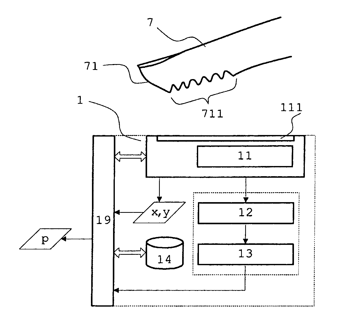
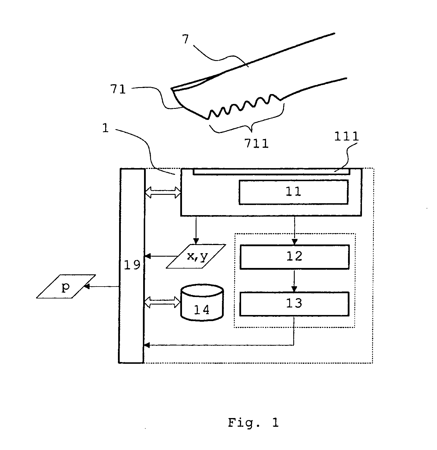
[0048]FIG. 1 illustrates a device which can be used to produce the pressure measurement device according to the invention. FIG. 1 shows a schematic representation of a device according to the invention for measuring pressure. A force is exerted by a subsurface 711 of an object 7 onto a contact area 111 of the pressure measurement device 1, and a corresponding pressure value parameter is generated. The reference 7 denotes an object, for example a finger or another human body part. This object 7 is distinguished in particular in that at least a part of the surface of the object 7 is elastically structured. The reference number 71 refers to the surface of the object 7. The reference 711 denotes a subsurface or surface region of this surface 71. The structures of the subsurface 711 may comprise patterns, arches and loops with ridges and grooves of the surface. Such structures of subregions 711, for example of a finger pad or the ball of a thumb, are used for example in dactyloscopy for ...


PUM


Abstract

A pressure measurement device and a pressure measurement method are provided, the pressure to be measured being exerted by an object onto a contact area of the pressure measurement device. The pressure measurement device comprises an image acquisition module having the contact area, image data of an elastically structured subsurface of the object being recorded. The pressure is determined and output according to the color and/or brightness values of selectively recorded image data. In particular, the invention relates to methods and devices for coordinate acquisition, navigation input, authentication of a user and for command and text input, embodied on a basis of the pressure measurement device according to the invention.

Description

CROSS REFERENCE TO RELATED APPLICATIONS[0001]The present patent application claims priority to the Patent Cooperation Treaty Application with the Serial No. PCT / EP2008 / 000334, that was filed on Jan. 17, 2008, which itself claims priority to the European Patent Application with the Serial No. EP 07005268.3 that was filed on Mar. 14, 2007, all the contents thereof being herewith incorporated by reference.BACKGROUND OF THE INVENTION[0002](a) Field of the Invention[0003]The present invention relates to a device and a method for measuring pressure, the pressure to be measured being exerted by an object onto a contact area of the pressure measurement device. In particular, the invention relates to methods and devices for coordinate acquisition, navigation input, authentication of a user and command and text input, embodied on the basis of the pressure measurement device.[0004](b) Brief Description of the Related Art[0005]A very wide variety of devices for measuring pressure have been know...

Claims


Application Information

Patent Timeline
IPC IPC(8): G06F3/041
CPCG06F3/0414G06K9/0012G06F21/32G06V40/1394
Inventor JACOMET, MARCELMULLER, LORENZGOETTE, JOSEFCATTIN, ROGEREICHER, ANDREASROLLIER, ALAIN
Owner AXSIONICS AG
Why Eureka
Try Eureka