Method and apparatus for transmitting uplink signal, and method and apparatus for generating uplink signal in communication system

a communication system and uplink signal technology, applied in the direction of multiplex communication, orthogonal multiplex, wireless communication, etc., can solve the problems of user interference, channel delay spread of any user may be greater,

Active Publication Date: 2010-03-18
ELECTRONICS & TELECOMM RES INST
View PDF6 Cites 41 Cited by
  • Summary
  • Abstract
  • Description
  • Claims
  • Application Information

AI Technical Summary

Benefits of technology

[0018]According to exemplary embodiments of the present invention, the interference between the uses and / or the interference between the cells can be randomized when the frequency domain CDM method is used.

Problems solved by technology

Accordingly, a channel delay spread of any user may be greater than the cyclic-shift in the cellular communication environment and so, the interference between users may occur.

Method used


Image

  • Method and apparatus for transmitting uplink signal, and method and apparatus for generating uplink signal in communication system
  • Method and apparatus for transmitting uplink signal, and method and apparatus for generating uplink signal in communication system
  • Method and apparatus for transmitting uplink signal, and method and apparatus for generating uplink signal in communication system

Examples


Embodiment Construction

[0031]In the following detailed description, only certain exemplary embodiments of the present invention have been shown and described, simply by way of illustration. As those skilled in the art would realize, the described embodiments may be modified in various different ways, all without departing from the spirit or scope of the present invention. Accordingly, the drawings and description are to be regarded as illustrative in nature and not restrictive. Like reference numerals designate like elements throughout the specification.

[0032]Throughout this detailed description and the claims which follow, unless explicitly described to the contrary, the word “comprise / include” or variations such as “comprises / includes” or “comprising / including” will be understood to imply the inclusion of stated elements but not the exclusion of any other elements. Each block is a unit for processing at least one function or operation, which can be realized by hardware, software, or a combination of har...


PUM


Abstract

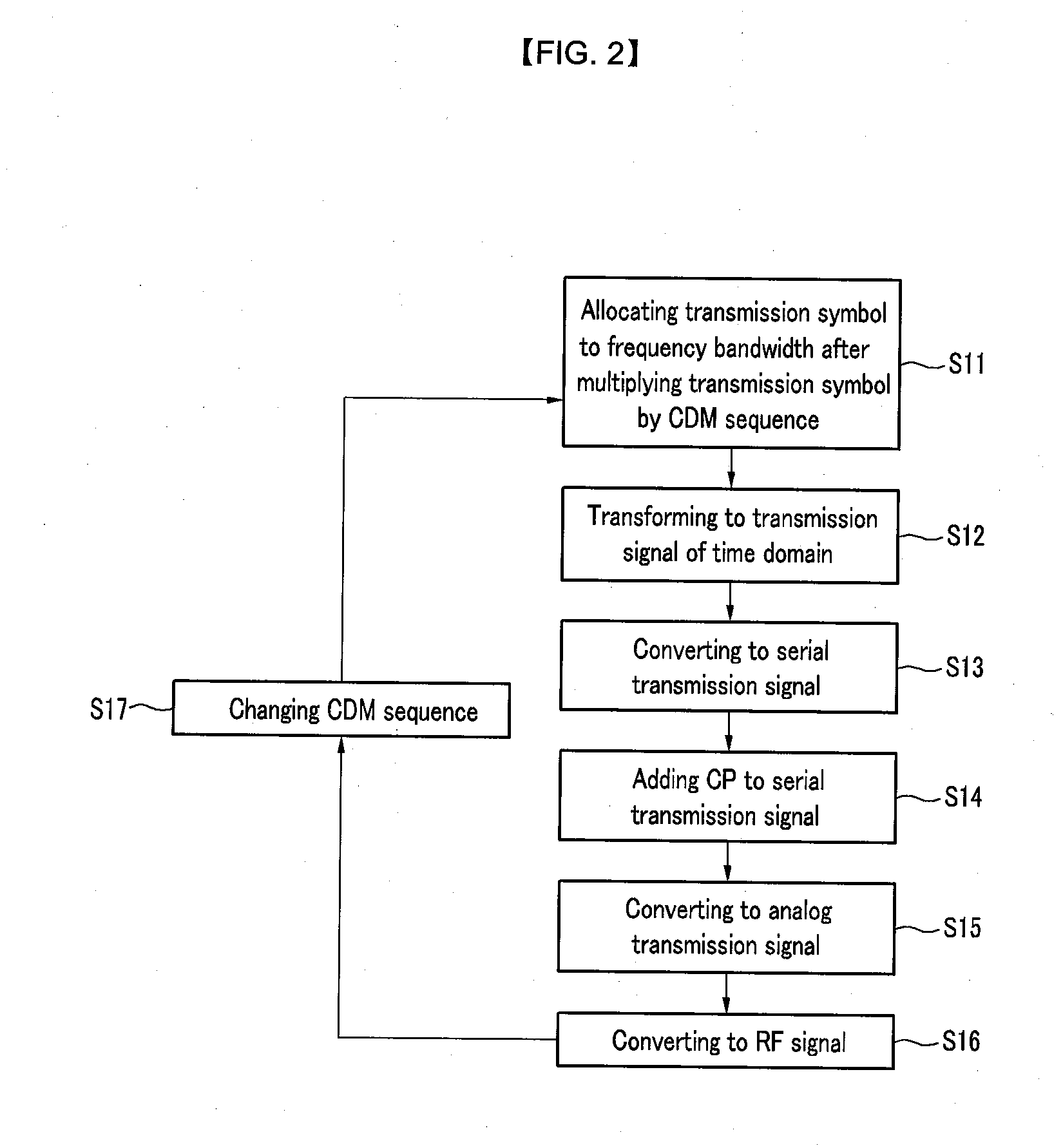
When a terminal generates an uplink signal in a communication system, the terminal hops a sequence for differentiating itself from another terminal with time. The terminal generates the uplink signal by multiplying a transmission symbol by a sequence of a transmission time corresponding to the transmission symbol.

Description

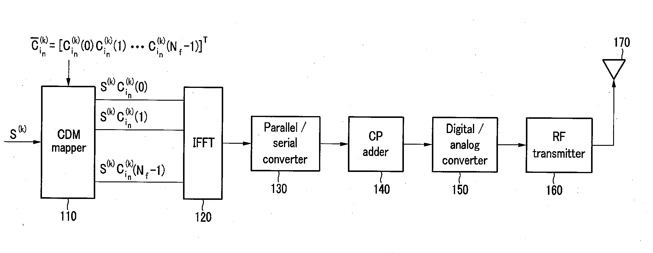
TECHNICAL FIELD [0001]The present invention relates to a method and an apparatus for transmitting an uplink signal, and a method and an apparatus for generating an uplink signal in a communication system.BACKGROUND ART [0002]In an orthogonal frequency division multiplexing (OFDM) based communication method, interference does not exist between different users since the different users use different frequencies for data channel. A method for using the different frequencies for the different users is referred to as frequency division multiplexing (FDM). However, code division multiplexing (CDM) that identifies the users by using codes is appropriate for a reference signal or a control channel. The CDM is superior to the FDM since the CDM can efficiently use resources for the reference signal or the control channel. The CDM is classified into a time domain CDM that directly spreads by OFDM symbol units and a frequency domain CDM that spreads in a frequency domain within one OFDM symbol....

Claims


Application Information

Patent Timeline
Patent Type & Authority Applications(United States)
IPC IPC(8): H04L27/00H04B1/69H04J13/00
CPCH04J11/00H04J13/0074H04L5/0021H04W72/04H04L5/0053H04L25/03866H04L27/2602H04L5/0048H04L1/1692H04L1/1861H04L1/1887H04J11/0026
Inventor PARK, HYEONG-GEUNKIM, II-GYUKO, YOUNG-JOCHANG, KAP-SEOKYI, HYO-SEOKKIM, YOUNG-HOONBANG, SEUNG-CHAN
Owner ELECTRONICS & TELECOMM RES INST
Why Eureka
Try Eureka