System, including a variable orifice assembly, for hydraulically managing pressure in a fluid distribution system between pressure set points

a technology of hydraulic adjustment and set points, applied in the direction of fluid pressure control, process and machine control, instruments, etc., can solve the problems of excessive pressure at the consumer's premises, large amount of water loss in the system, and increase in water loss. , to achieve the effect of reducing the amount of water loss

Inactive Publication Date: 2010-03-25
CLA VAL
View PDF7 Cites 20 Cited by
  • Summary
  • Abstract
  • Description
  • Claims
  • Application Information

AI Technical Summary

Benefits of technology

[0008]The present invention resides in a system and method for hydraulically managing fluid pressure downstream of a main valve. As will be more fully described herein, the system is flow-driven and responds to changing flow demand downstream from a main valve, so as to manage and control the fluid pressure downstream f

Problems solved by technology

The amount of water loss in the system is due to a variety of leak sources, such as improperly tightened pipe flange connections, leaking flange gaskets, leaking valve seals, failed seals, old pipes (with pinhole bursts), loose fittings, leaky faucets, etc.
The sum of these sources of leakage can add up to a substantial amount of water loss.
Maintaining the entry point pressure at all times at the level necessary to provide adequate pressure at the distant points for periods of high demand can result, during periods of low demand, in excessive pressure at the consumer's premises, and thus increased waste of water by unnecessary consumption and leakage.
Automatic pressure reducing valves are used in water distribution systems to reduce pressure to a pre-determined value or sub-point that is adequate, but does not expose normal components, such as household hot water tanks, to overpressure.
Under low demand conditions, not

Method used


Image

  • System, including a variable orifice assembly, for hydraulically managing pressure in a fluid distribution system between pressure set points
  • System, including a variable orifice assembly, for hydraulically managing pressure in a fluid distribution system between pressure set points
  • System, including a variable orifice assembly, for hydraulically managing pressure in a fluid distribution system between pressure set points

Examples


Embodiment Construction

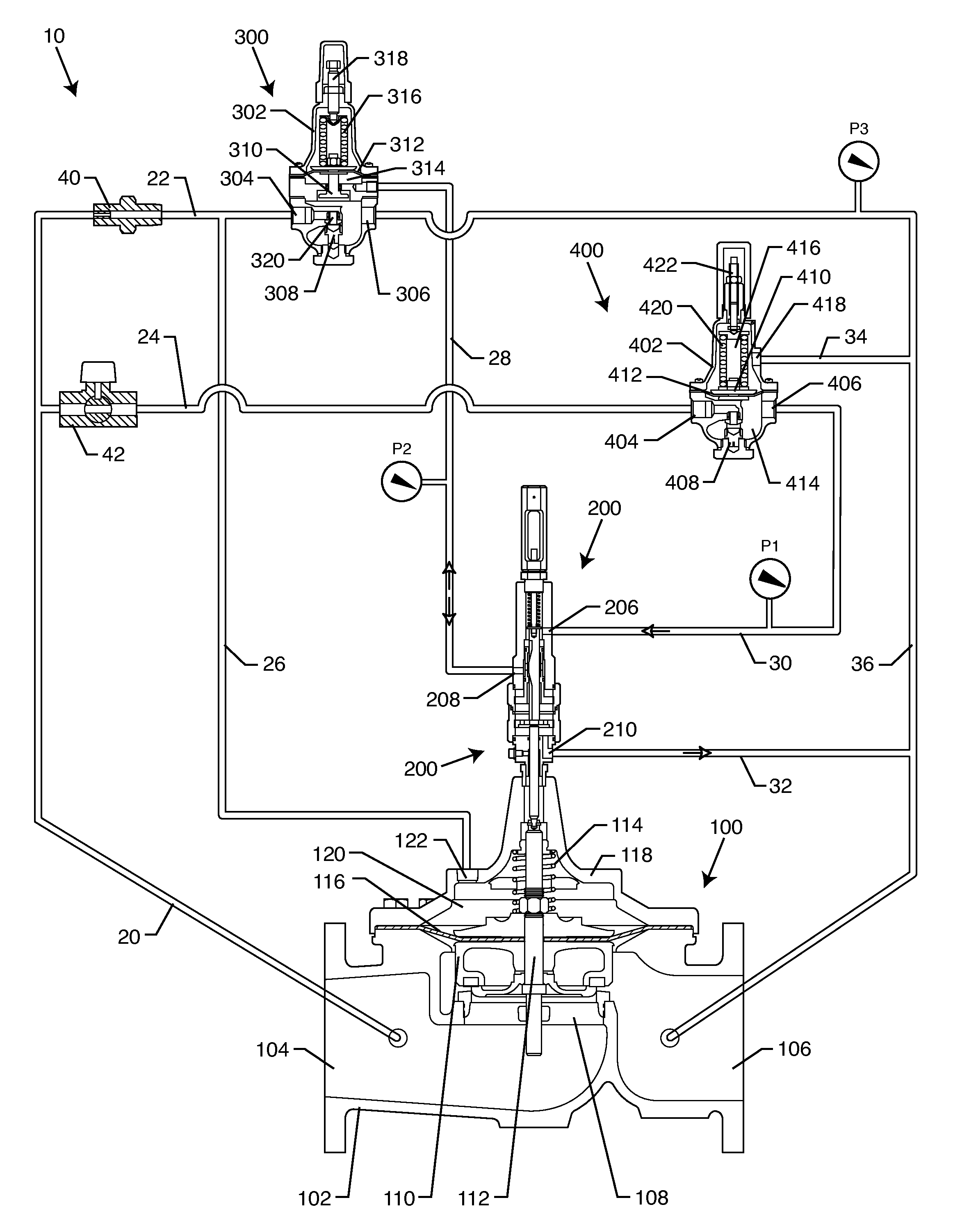
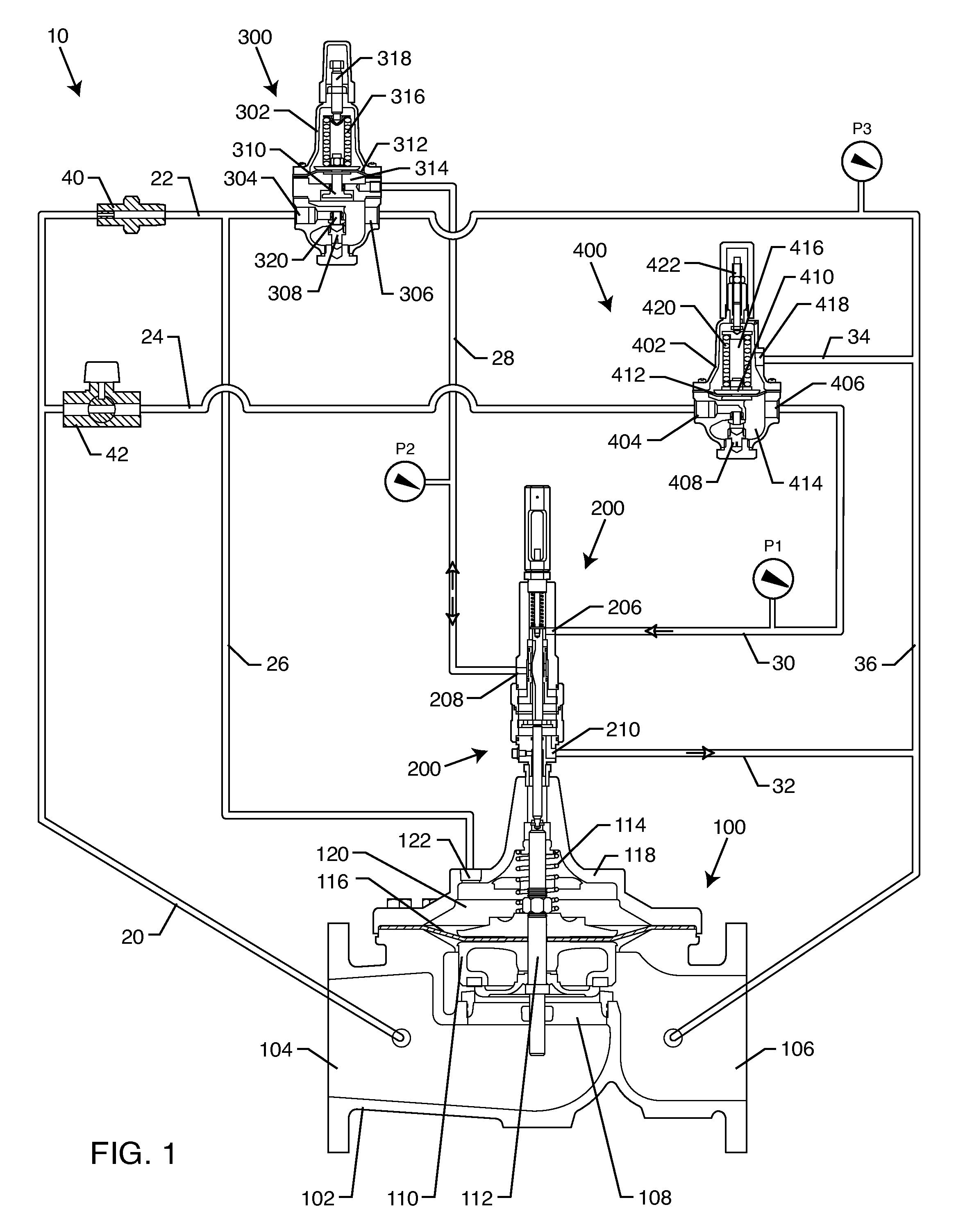
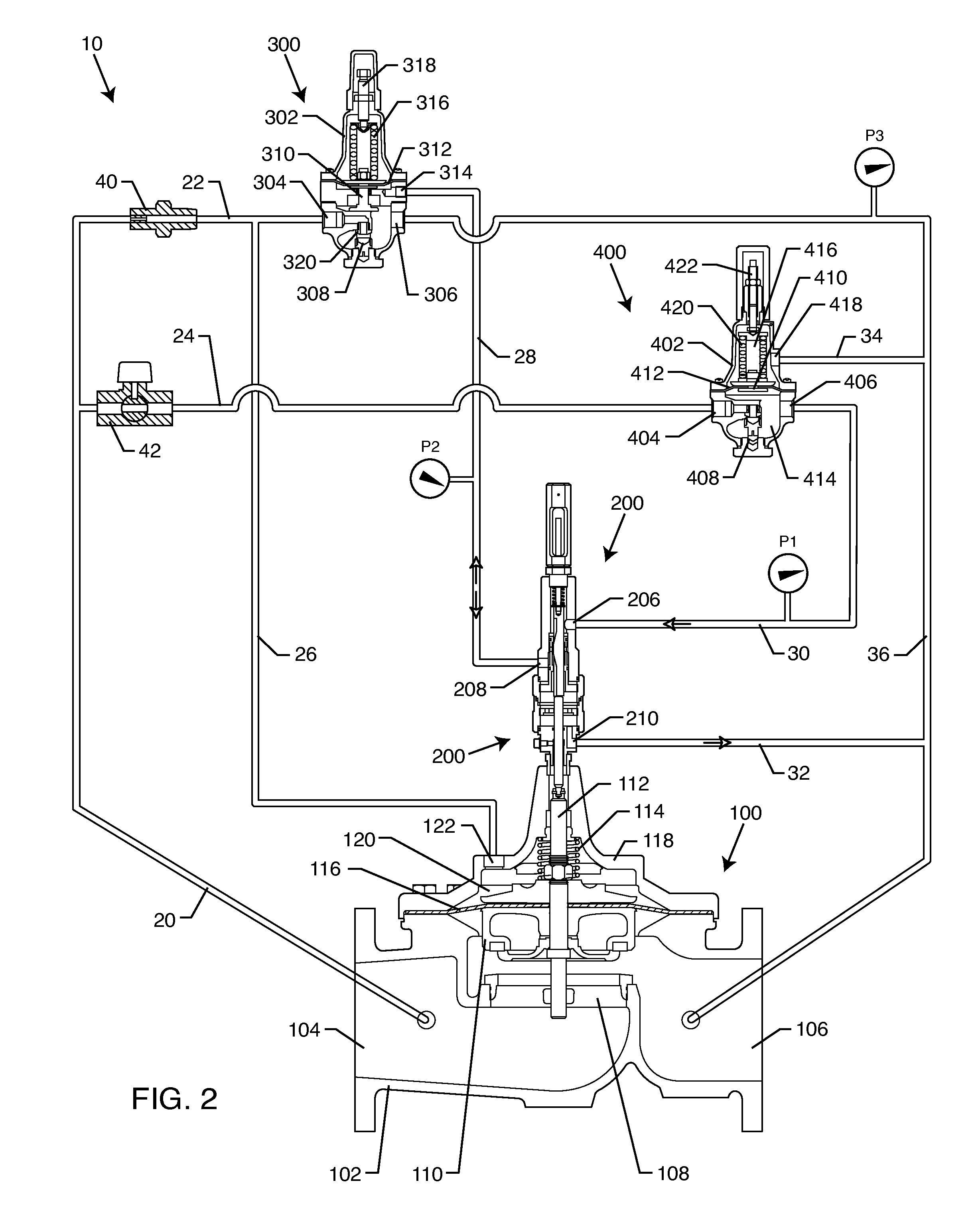
[0028]As shown in the accompanying drawings, for purposes of illustration, the present invention is directed to adjustable hydraulically operated pressure management control valve systems. As will be more fully described herein, the present invention is directed to a system for hydraulically managing fluid pressure in a fluid distribution system between pressure set points so as to manage fluid pressure downstream of a main valve of the fluid distribution system. The systems of the present invention are particularly adapted for use in the waterworks industry where there is a desire to reduce the amount of water loss in the system due to leaks. The invention can reduce the amount of water loss in a system by reducing the system pressure as the flow or system demand decreases. A common example would be a residential water system where water demand is high during the day and low at night. If the pressure is lower during low usage, then a lower pressure will result in lower water losses...


PUM


Abstract

A system for hydraulically managing fluid pressure in a fluid distribution system between pressure set points includes a main valve having a fluid inlet and outlet. The main valve is configured to open to increase fluid flow therethrough and to close to reduce the fluid flow therethrough. A variable orifice assembly is coupled to the main valve and has fluid apertures formed in a housing thereof to create a fluid flow pathway therebetween. A valve stem is variably positioned within the housing to alter the fluid flow between the fluid apertures. A first control pilot is in fluid communication with the main valve and a first fluid aperture of the variable orifice assembly. A second control pilot is in fluid communication with the main valve and a second fluid aperture of the variable orifice assembly. The valve position and fluid flow are variable as the main valve opens and closes.

Description

BACKGROUND OF THE INVENTION[0001]The present invention generally relates to automatic valves, such as those employed on municipal water utility systems. More particularly, the present invention relates to a system for hydraulically adjusting and managing pressure between set points so as to control pressure downstream of a main valve in such a fluid distribution system.[0002]There is a general understanding throughout the worldwide water supply industry that instances of water loss are common in many water distribution networks and in many instances the level of water loss can be relatively high. The amount of water loss in the system is due to a variety of leak sources, such as improperly tightened pipe flange connections, leaking flange gaskets, leaking valve seals, failed seals, old pipes (with pinhole bursts), loose fittings, leaky faucets, etc. The sum of these sources of leakage can add up to a substantial amount of water loss. Maintaining the entry point pressure at all times...

Claims


Application Information

Patent Timeline
IPC IPC(8): G05D16/16F16K31/12
CPCG05D16/163F16K31/365F16K17/105Y10T137/7764Y10T137/8659
Inventor FOLK, ROBERTRE, DANIEL
Owner CLA VAL
Why Eureka
Try Eureka