Construction machine

a construction machine and construction technology, applied in the field of construction machines, can solve the problems of complicated tank mounting structure, and more troublesome tank mounting work, and achieve the effect of stabilizing the fixed state of the tank and suppressing the vibration of the tank

Inactive Publication Date: 2010-03-25
KOBELCO CONSTR MASCH CO LTD
View PDF10 Cites 6 Cited by
  • Summary
  • Abstract
  • Description
  • Claims
  • Application Information

AI Technical Summary

Benefits of technology

[0030]In this case, since the vibration isolating plate made of rubber is disposed between the lower surface of the tank and the tank supporting surface, not only the vibration of the tank can be suppressed effectively with both downward pressing force and the vibration isolating plate, but also the fuel tank can be pressed down more strongly with a repulsive force of the vibration isolating plate.
[0031]Further, since motion of the lower portion of the tank can be suppressed by utilizing the drain plate provided on the lower surface of the fuel tank, it is possible to further stabilize the fixed state of the tank.

Problems solved by technology

As a result, not only the tank mounting structure becomes complicated, but also the tank mounting work is troublesome.
According to the related art, moreover, the tank fixing portions are specified, so particularly in the case of a plastic fuel tank, the tank mounting work becomes more troublesome due to dimensional variations and deformations.
Further, there also has been the problem that the fastening means are apt to become loose.

Method used


Image

  • Construction machine
  • Construction machine
  • Construction machine

Examples


Embodiment Construction

[0039]An embodiment of the present invention will be described below with reference to FIGS. 1 to 5.

[0040]In this embodiment the present invention is applied to a compact excavator according to the foregoing description of the background art.

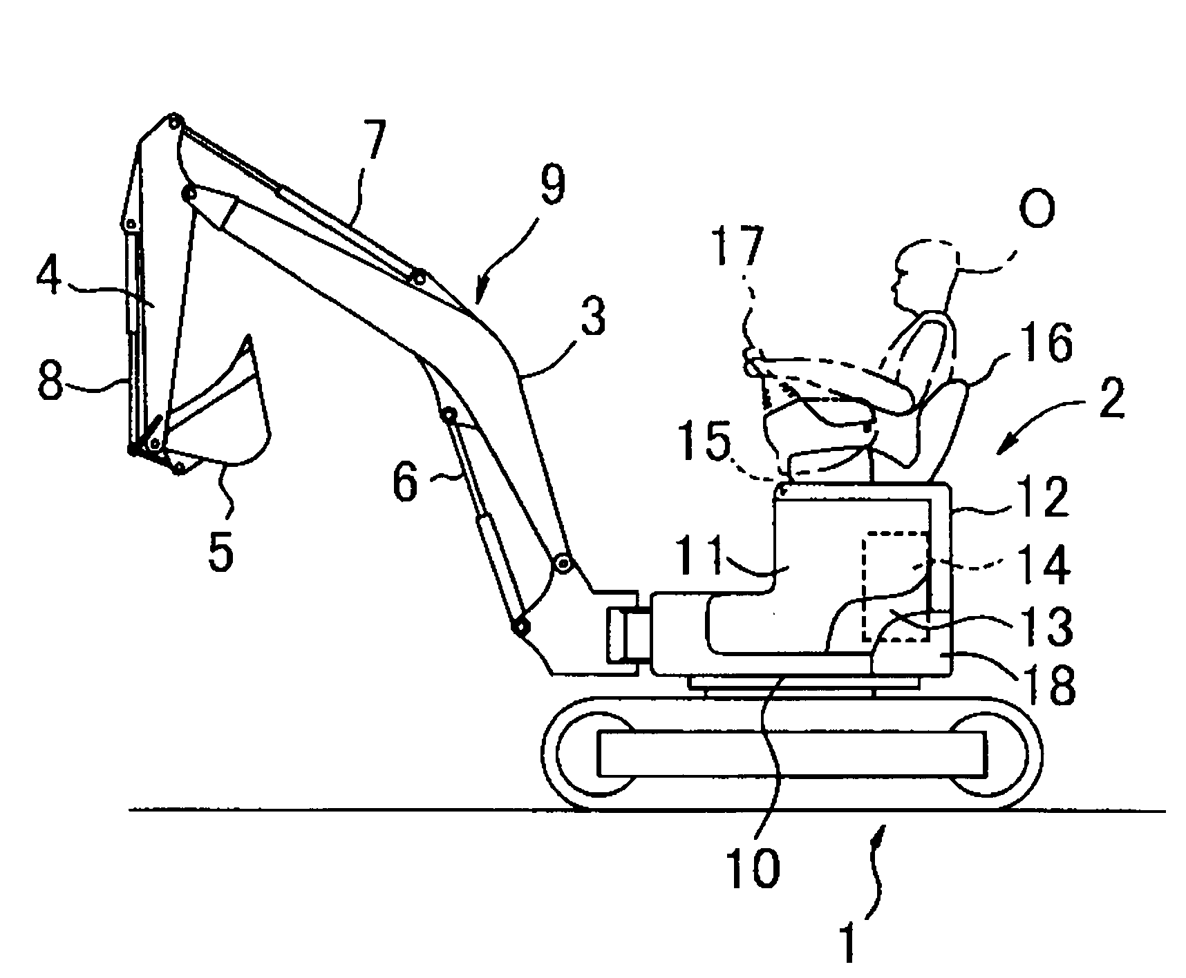
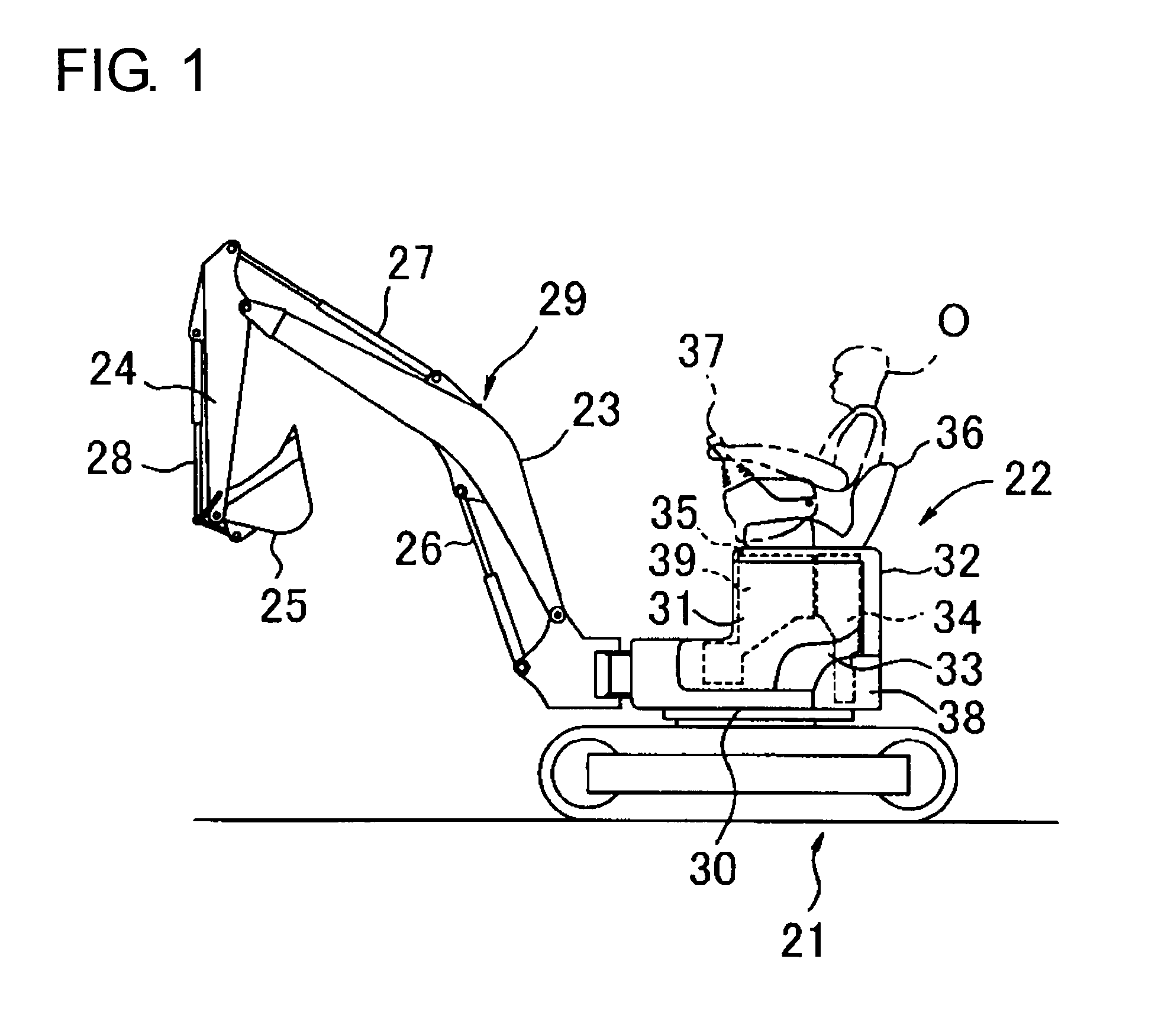
[0041]FIG. 1 shows a schematic structure of an entire compact excavator as seen from a side face thereof.

[0042]In this embodiment the following points are the same as in the compact excavator shown in FIGS. 6 and 7.

[0043](i) In the compact excavator, an upper rotating body 22 is mounted rotatably on a crawler type lower traveling body 21 and working attachments 29 comprising a boom 23, an arm 24, a bucket 25 and hydraulic cylinders (boom cylinder, arm cylinder, bucket cylinder) 26-28 for actuating the boom, arm and bucket respectively are attached to the upper rotating body 22.

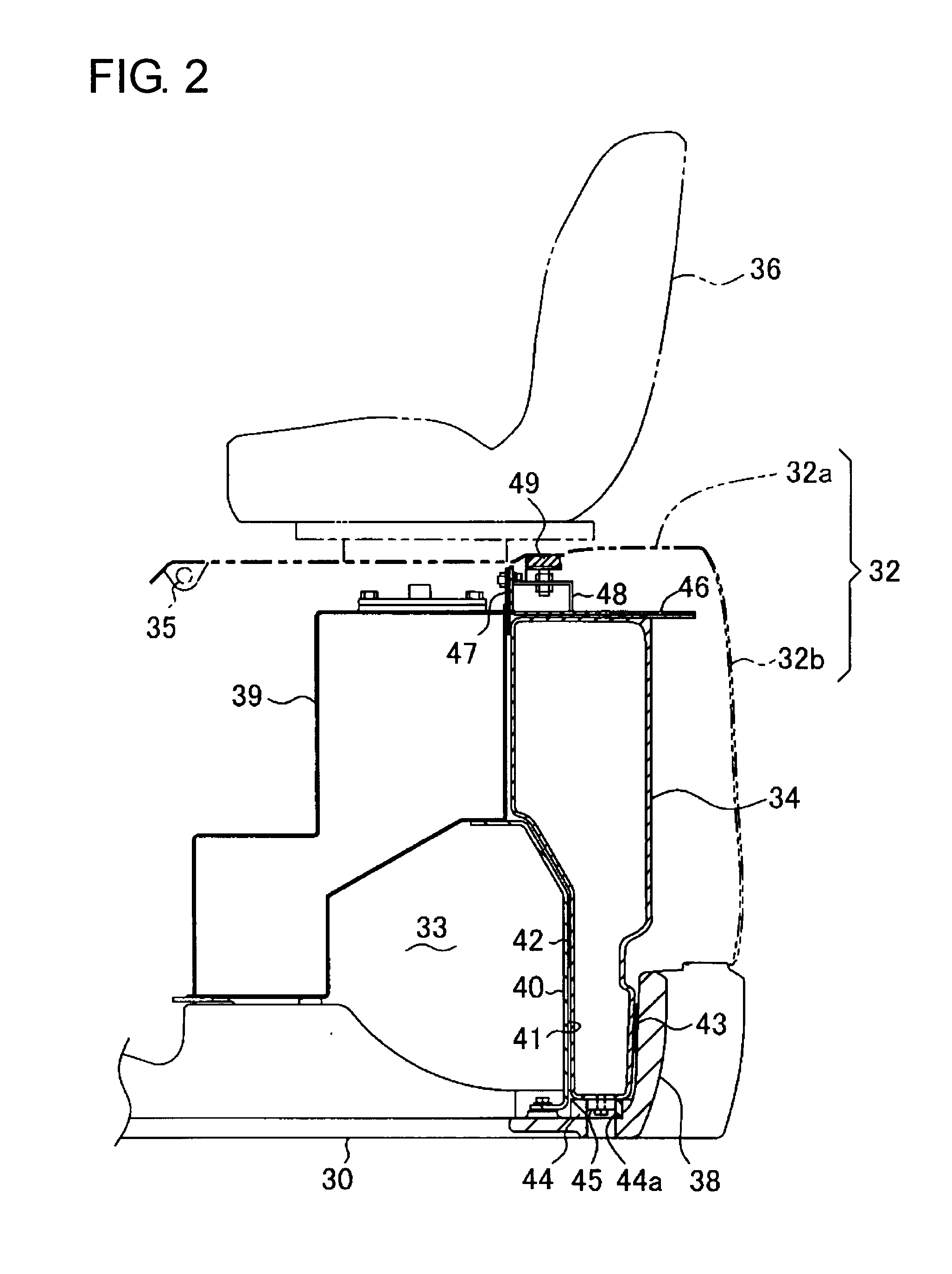
[0044](ii) An engine room 33 (a tank accommodating space recited in claims), which is enclosed with right and left side panels (only one-side panel is shown) 31 and a bonn...


PUM


Abstract

In a compact excavator of the type wherein an opening portion of an engine room with a fuel tank installed therein is opened and closed with a bonnet and an operator's seat is provided on the bonnet, a load transfer member is provided on an upper surface of the fuel tank in a state in which a load receiving portion is in contact with the bonnet, so that a total load comprising the weight of the operator's seat, the weight of an operator sitting on the operator's seat and the weight of the bonnet is transmitted from the bonnet to the fuel tank as a force of pressing down the tank from above.

Description

BACKGROUND OF THE INVENTION[0001]1. Field of the Invention[0002]The present invention relates to a construction machine wherein a tank accommodating space with a fuel tank accommodated therein is covered with a bonnet from above and wherein an operator's seat is provided on the bonnet.[0003]2. Description of the Related Art[0004]With a small-sized hydraulic excavator (compact excavator) as an example, which is a suitable example of the present invention, a description will be given below about the background art.[0005]In a compact excavator, as shown in FIGS. 6 and 7, an upper rotating body 2 is mounted rotatably on a crawler type lower traveling body 1 and a working attachment 9 comprising a boom 3, an arm 4, a bucket 5 and hydraulic cylinders (boom cylinder, arm cylinder, bucket cylinder) 6 to 8 for actuating those boom, arm and bucket respectively are attached to the upper rotating body 2.[0006]An engine room 13 (a tank accommodating space recited in claim 1), which is enclosed w...

Claims


Application Information

Patent Timeline
Patent Type & Authority Applications(United States)
IPC IPC(8): B60K26/00
CPCB60K15/063B60K15/067E02F9/166B62D25/10E02F9/0883B60N2/015
Inventor MIYACHI, ISAO
Owner KOBELCO CONSTR MASCH CO LTD
Why Eureka
Try Eureka